2.2 Selecting the Right Dither Strategy
The dithering strategies outlined in this section are guidelines, not solid rules. There will likely be science programs that do not neatly fit into any one of these dithering categories. If answers to your question are not found in this document, the Phase II Proposal Instructions, instrument web pages, and the Astronomer's Proposal Tool (APT), please get in touch with your Contact Scientist or submit a ticket via the HST Help Desk portal.
Dealing with Cosmic Rays, Hot Pixels, Undersampling, and Photometric Accuracy
During the Phase II proposal writing stage, users are faced with the challenge of crafting the best possible observing program within the allocated telescope time. For instance, a long observation broken into multiple dithered exposures comes at a cost: increased readout noise and less total science exposure time (due to observational overheads). How much of that cost can be incurred without compromising science goals? That depends on the purpose of the observations: is it to detect an unknown underlying structure in the field? Is high spatial resolution a priority? Is there a requirement for highly accurate photometry?
Designing an observing program to get the best quality data depends on how to deal with cosmic rays, hot pixels, spatial sampling, and signal-to-noise.
- Cosmic rays: a minimum of two exposures, preferably three or more, is the most effective way to reduce the number of cosmic ray hits at the same detector location in each exposure (according to the binomial distribution). Even with two exposures, it's possible to get overlapping cosmic ray hits in the two images. In the example below, generated using the WFPC2 Exposure Time Calculator, a 3000 second exposure for a 24 magnitude point source in F122M with gain of 7 is broken into several sub-exposures to show how the number of overlapping cosmic ray pixels is reduced as more sub-exposures are used for the combined image, but at the cost of decreased signal-to-noise. (Items in parenthesis are additional comments). A 3000 second exposure would lose about 61,000 pixels per chip to cosmic ray hits. If two 1500 second images were combined, the number of cosmic ray-affected pixels drops dramatically to 1400 per chip. If three 1000 second images were combined, only 21 pixels per chip would be affected by cosmic rays.
Table 2.1: WFPC2 Exposure Time Calculator Shows Changes in SNR and Cosmic Rays Based on Number of Split Exposures
Number of sub-exposures | Total SNR | Pixels Lost | Comments |
|---|---|---|---|
| (No Split) | 3.7 | 9.606250% | (about 61,000 pixels) |
| 2 | 2.9 | 0.230700% | (about 1400 pixels) |
| 3 | 2.5 | 0.003283% | (21 pixels) |
| 4 | 2.3 | 0.000033% | |
| 6 | 1.9 | 0.000000% |
- Hot Pixels: flat-field calibrated images (
flt.fits/flc.fits) from the archive are processed with dark reference files that contain hot pixel information for a time period during which the observation was obtained. (It usually takes a few weeks for the most up-to-date dark reference files to catch up with the science observations. If you retrieve images taken within a month to six weeks of execution, chances are that the dark reference file used to calibrate the data does not match the observation date.) Since some hot pixels are variable on very short timescales, they are not flagged in dark reference files. Therefore, the easiest way to remove hot pixels is to dither the images. A two-point dither with small integer shifts is enough to remove most hot pixels. - Undersampling: HST cameras, with exception of the ACS/HRC, have detector pixel widths comparable to the FWHM of the point spread function (PSF). Drizzle-combining images that are shifted by sub-pixel amounts can improve PSF sampling, (in other words, increase spatial resolution). Generally, sub-sampling by a small shift with a 1/2-pixel offset provides the best improvements over non-dithered images. In some cases, observers may wish to further explore the limits of the instrument and spacecraft pointing accuracy by considering small shifts with 1/3-pixel offsets. The extent to which such refinements can be explored depends primarily upon the number of orbits available and the instrument being used.
A Top-level View of Dithering Strategies
Decisions on how to implement dithering in your observing proposal depends on many factors, some of which were discussed in the previous section, others that will be explained later in this chapter. With the exception of mosaic dithers, dither step sizes are kept small to minimize differential geometric distortion between the images but also need to be large enough to remove chip gaps (ACS/WFC, WFC3/UVIS, WFCP2) or artifacts like blobs and the death star (WFC3/IR).
This keeps the step size at each position in each image more nearly the same so that every pixel gets as close to the same level as possible of subpixel sampling as intended by the dither pattern. At a top level, there are several dithering categories:
- Some types of observations may be unsuitable for dithering
- Very Short Exposures: if each target is observed for less than a few minutes, extra overhead from dithering could significantly impact the overall signal-to-noise (S/N) that may offset advantages gained from dithering.
- Critical photometric measurements: for high-precision time-dependent photometric monitoring, dithering may introduce additional complications due to intra-pixel sensitivity variations. Therefore, some observers may prefer to obtain all the images at a single pointing location.
- Simple Dithering: dithering each exposure by integer pixel shifts reduces the impact of hot pixels in the final combined image. Furthermore, spatial sampling can be improved with two- or three-point subpixel dithering. For programs allocated about one orbit per target per filter, at least two to three exposures should be obtained to facilitate cosmic ray rejection. If one is interested in targets throughout the field, rather than one single small target, cosmic ray removal will need to be more rigorous, and a larger number of exposures will be required. The instrument handbooks give expected cosmic ray rates for each of the imaging instruments.
- Full Dithering: for improved spatial sampling, a "full" four-point dither, with 1/2 pixel subsampling along both detector axes, is recommended. Most of the subpixel information in an image can be recovered by a four-point dither. Deep programs may benefit from an even larger numbers of dithers. Obtaining a four-point dither across the field of view limits the user to small dithers because of the distortion of many HST cameras. At the same time, the user may want to remove features such as the slit between the two chips on ACS with a large dither. The user may want to combine several sets of four-point dithers in this case. In addition, in cases where there are small objects with high signal-to-noise, image quality can be improved by using dithering patterns sampled finer than four points.
- Dithering for Parallel Images: it is not always possible to obtain optimal dithers simultaneously for primary and parallel instruments due to the large separation between detectors, and different pixel scales. Uniformly-spaced dithers for the primary instrument generally yield non-uniform dithers for the parallel instrument. Indeed, a recent ISR (ACS 2023-04/WFC3 2023-05) investigates the effectiveness of the existing dither patterns in APT for use on prime+parallel observations with ACS and WFC3 and finds that patterns that were optimized for one detector often result in poor sub-pixel phase sampling in another. The report provides new dither patterns for use with prime+parallel observations which have good sub-pixel phase sampling in both instruments. For now, these dither patterns must be input into the APT manually in the form of POS TARGs.
- Dithering in WFPC2: the Planetary Camera (PC) and Wide Field Cameras (WFC) had different scales; therefore, a dither pattern was developed to implement subpixel dithering in both camera types.
Selecting the Number of Dither Pointings and Step Sizes
Dithering requires a noticeable amount of spacecraft overhead with each dither offset typically adding about two to three minutes of overhead to the total observing plan. Outlined below are recommendations for various observing goals.
Integer-Spaced Dither Steps
Two to three integer-spaced dither steps will, in most cases, correct the effects of hot pixels. If the flux from an object fell on a hot pixel in one image, chances are good that it will fall on a normal pixel in the other dithered image.
Sub-pixel Dithering
Strategies and issues for sub-pixel dithering are covered in the remainder of this section. The number of sub-pixel dithers for an observation depends on the amount of available observing time and project goals.
- The simplest type of sub-pixel dither is a two-point dither offset along only one axis; this is used in STIS long-slit spectroscopy for subsampling along the (spatial) slit direction. For example, one exposure would be obtained at the original pixel position of (0,0) and a second obtained at (0,n+1/2) pixels where n is an arbitrary integer value.
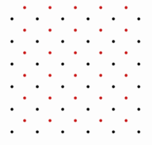
- For imaging, a two-point sub-pixel dither starting at the original pixel position of (0,0), followed by a second image shifted by (n+1/2, m+1/2), where n and m are arbitrary integer values, will provide a substantial increase in information over non-dithered data. For square detector pixels, this dither pattern results in sampling that would be produced by an array with a pixel size that's \sqrt{2} smaller than the original array, rotated by a 45angle from the original orientation. Setting n and m to a small integer value, around 5 to 10, will also allow the removal of hot pixels. Figure 2.1 shows the sampling by the WFC3 IR detector on the sky (note the slightly rectangular pixels), and Figure 2.2 shows the sampling produced by introducing a two-point dither. The original placement is shown in black, the second dither is in red.
WFC3 and ACS pixels are not square pixels.
Figure 2.1: The Sampling of the WFC3 IR Detector on the Sky

Figure 2.2: The Sampling Produced by Introducing a Two-point Dither Using the WFC3 IR Detector.
- A four-point dither yields a total of 4 images that have 1/2-pixel offsets in x and y, as well as small integer shifts (n, m) to reduce the effect of hot pixels: (0,0), (0,m+1/2), (n+1/2,m+1/2), (n+1/2,0). This yields uniform tiling along the x- and y-axis with half-pixel offsets, providing a more robust and powerful sub-sampling of the PSF. In fact, given the native sampling of HST instruments, an accurate four-point dither recovers nearly all of the information available in an image (see Figure 2.3).
Figure 2.3: A Four-point Dither
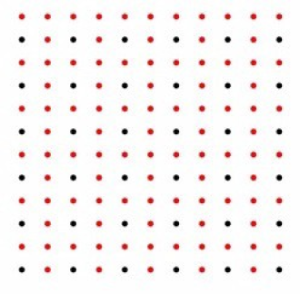
Figure 2.4: A Three-point Dither Applied to the WFC3 NIR Detector
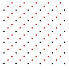
- Use of a three-point dither may arise for cases where the available observing time breaks down more naturally into blocks of three exposures, instead of two or four. However, the best placement for a three-point dither is not obvious because there is no natural way to tile the plane using three placements of a rectangular detector grid. Two- and four-point dither patterns described earlier minimize the largest distance of any point on the image plane to the nearest dither location. For a three-point dither this can be accomplished with offsets along the diagonal of (0,0), (1/3,1/3), and (2/3,2/3) pixels. Again, additional integer offsets of a few pixels should be added to help remove detector defects. Figure 2.4 shows a three-point dither applied to the WFC3/IR detector.
- If the goal is to obtain extremely accurate PSFs from observations spanning several orbits, users may consider an even finer subsampling of the pixel. An eight-point dither could be performed by crossing a four-point dither with a two-point dither; in other words, a secondary dither pattern at the location of each point in a primary dither pattern. That secondary dither should be a two-point dither of the form (m1/4,n1/4) which would place a point in the center of each "square" created by the primary four-point dither pattern. Note, however, that differential distortion across the field can mean that unless the integer offsets are small, a well-planned dither strategy for the center of the chip will perform worse near the edges where the distortion will result in a dither pattern that varies significantly from the center of the chip. The four-point dither, if performed accurately with the loss of few pixels to cosmic rays or other defects, recovers nearly all the spatial information in an HST image. Therefore, users of instruments like ACS/WFC may prefer to cross a small four point dither with a larger two or three point dither that will cover the gap between the chips. The four point dithers will insure good sub-sampling in the final combined image.
- A number of WFC3 users have inquired about dithers in multiples of three because they find that three exposures fit well into a single orbit. One option is to create a nine-point dither by dividing the original pixel with a 3 × 3 grid.
A three-point dither with another three-point secondary dither at each point: (0,0), (0,a+1/3), (0,a+2/3), (m,m), (m+a+1/3), (m+a+2/3), (n,n), (n+a+1/3), (n+a+2/3), where (0,0), (m,m), (n,m) is a three-line dither with integer steps, and 'a' is a small integer added to the fractional shift.
Forming a six-point dither, however, is less clear. A calculation suggests that crossing the linear three point dither, described above, with a (1/2,0) two-point dither is the optimal strategy. For square pixels, the half-pixel dither could be taken in either direction. But WFC3 IR pixels are slightly longer in the x-direction, so the dither should be performed along the x-axis. In Figure 2.5, the black points show a single WFC3 image; the red points show the two additional dithers to form a single three-point dither; the blue points show the additional three-point dither to form the six-point dither.
Figure 2.5: A Six-point Dither
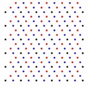
The six-point dither: (0,0), (0,m+a+1/2), (m,m), (m+a+1/2), (n,n), (n+a+1/2) where (0,0), (m,m), (n,m) is a three-line dither with integer steps, and "a" is a small integer added to the fractional shift.
Data with Inaccurate Offsets in Position or Roll Angle
On rare occasions, pointing errors may occur during guide star re-acquisitions within a visit. As a result, images in the same visit cannot be aligned based on their WCS information. This will be evident in pipeline drizzle-combined images that may show double objects, elongated PSFs indicating sub-pix misalignments, and artifacts like "chopped" PSFs. DrizzlePac tasks such as TweakReg can be used to measure and correct the offsets between images, so they can be properly aligned and reprocessed with AstroDrizzle.
How Many Images to Obtain at Each Dither Location
In general, most cosmic rays can be removed with one image at each dither pointing. It is the best approach for small programs (one orbit per target) that require sub-pixel dithering, and for programs that require low read noise (such as narrow-band imaging of extremely faint sources). For larger programs, or for programs where read noise is not a serious issue, users can opt for slightly improved sampling by executing a small secondary sub-pixel dither at each pointing of a larger primary dither pattern or they could choose to obtain multiple exposures at each primary dither pointing. Implementing multiple exposures at each dither position insures that cosmic ray rejection can be performed in all pixels of each image, whereas dithered observations will result in only one image on the edges of the combined image and making identification of cosmic rays by AstroDrizzle impossible in those regions.
Dithering Considerations for HST Instruments
To ensure this information is kept up to date, links to the dithering strategies for various instruments are provided in this section.
Additional information is available in the Phase II Proposal Instructions, Chapter 7: Pointings and Patterns for ACS, WFC3, and STIS.
A recent ISR (ACS 2023-04/WFC3 2023-05) investigates the effectiveness of the existing dither patterns in APT for use on prime+parallel observations with ACS and WFC3 and finds that patterns that were optimized for one detector often result in poor sub-pixel phase sampling in another. The report provides new dither patterns for use with prime+parallel observations which have good sub-pixel phase sampling in both instruments. For now, these dither patterns must be input into the APT manually in the form of POS TARGs.