1.4 Technical Overview
1.4.1 The Instrument
The FGS is a white-light shearing interferometer. It differs from the long-baseline Michelson Stellar Interferometer in that the angle of the incoming beam with respect to the HST’s optical axis is measured from the tilt of the collimated wavefront presented to the “Koesters prism” rather than from the difference in the path length of two individual beams gathered by separate apertures. Thus, the FGS is a single aperture (single telescope) interferometer, well suited for operations aboard HST. In addition, the FGS is a two dimensional interferometer; it scans or tracks an object’s fringes in two orthogonal directions simultaneously. As a science instrument, the FGS can observe targets as bright as V=3 and as faint as V=17.0 (dark counts dominate for V>17 targets).
1.4.2 Spectral Response
The FGS employs photomultiplier tubes (PMTs) for detectors. The PMTs—four per FGS—are an end-illuminated 13-stage venetian blind dynode design with an S-20 photocathode. The PMT sensitivity is effectively monotonic over a bandpass from 4000 to 7000A, with an ~18% efficiency at the blue end which diminishes to ~2% at the red end.
Each FGS contains a filter wheel fitted with 5 slots. FGS1r contains three wide-band filters, F550W, F583W (sometimes called CLEAR), F605W, a 5-magnitude Neutral Density attenuator (F5ND), and a 2/3 pupil stop, referred to as the PUPIL. Only the F583W and the F5ND are supported by standard calibrations for science observations. The PUPIL is calibrated for guide duty. Transmission curves of the filters and recommendations for observing modes are given in Chapter 2 and Chapter 4 respectively.
1.4.3 The S-Curve: The FGS’s Interferogram
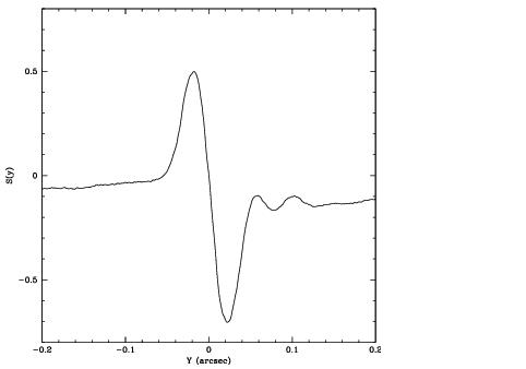
The FGS interferometer consists of a polarizing orthogonal beam splitter and two Koesters prisms. The Koesters prism, discussed in Chapter 2, is sensitive to the tilt of the incoming wavefront. Two beams emerge from each prism with relative intensities correlated to the tilt of the input wavefront. The relation between the input beam tilt and the normalized difference of the intensities of the emergent beams, measured by pairs of photomultiplier tubes, defines the fringe visibility function, referred to as the “S-Curve”. Figure 1 shows the e from a point source. To sense the tilt in two dimensions, each FGS contains two Koesters prisms oriented orthogonally with respect to one another. A more detailed discussion is given in Chapter 2.
1.4.4 FGS1r and the AMA
During the Second Servicing Mission in March 1997 the original FGS1 was replaced by FGS1r. This new instrument was improved over the original design by the re-mounting of a flat mirror onto a mechanism capable of tip/tilt articulation. This mechanism, referred to as the Articulated Mirror Assembly, or AMA, allows for precise in-flight alignment of the interferometer with respect to HST’s OTA. This assured optimal performance from FGS1r since the degrading effects of HST’s spherically aberrated primary mirror would be minimized (the COSTAR did not correct the aberration for the FGSs). This topic is discussed in detail in Chapter 2.
1.4.5 Field of View
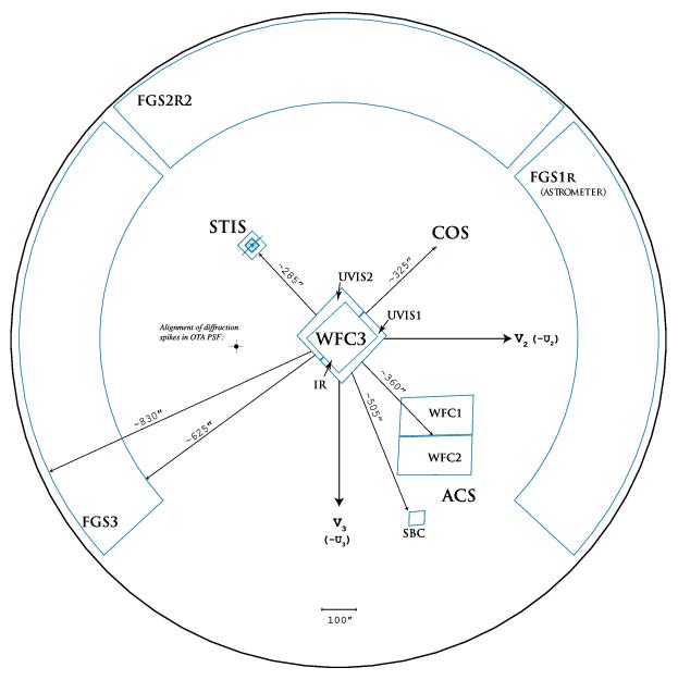
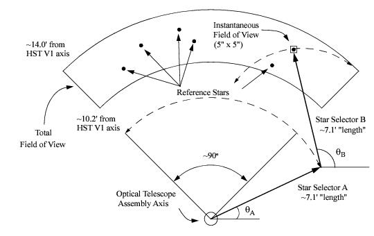
The total field of view (FOV) of an FGS is a quarter annulus at the outer perimeter of the HST focal plane with inner and outer radii of 10 and 14 arcmin respectively. The total area (on the sky) subtended by the FOV is ~ 69 square arcmintues. The entire FOV is accessible to the interferometer, but only a 5 × 5 arcsec aperture, called theInstantaneous Field of View (IFOV), samples the sky at any one time. A dual component Star Selector Servo system (called SSA and SSB) in each FGS moves the IFOV to a desired position in the FOV. The action of the Star Selectors is described in detail in Chapter 2, along with a more detailed technical description of the instrument. Figure 1.2 shows a schematic representation of the FGSs relative to the HST focal plane after Servicing Mission 4.
1.4.6 Modes of Operation
The FGS has two modes of operation: Position mode and Transfer mode.
Position Mode
The FGS Position mode is used for relative astrometry, i.e. parallax, proper motion, reflex motion and position studies. In Position mode, the HST pointing is held fixed while selected FGS targets are sequentially observed (fringes are acquired and tracked, see Appendix A:Target Acquisition and Tracking) for a period of time (2 < t < 120 sec, selected by the observer) to measure their relative positions in the FOV. Two-dimensional positional and photometric data are continuously recorded every 25 msec (40 Hz). The raw data are composed of a Star Selector encoder angles (which are converted to FGS X and Y detector coordinates during ground processing) and photomultiplier (PMT) counts. Figure 1.3 is a schematic of the FGS FOV and IFOV. The figure shows how Star Selectors A and B uniquely position the IFOV anywhere in the FGS FOV.
Transfer Mode
In Transfer mode, the FGS obtains an object’s interferograms in two orthogonal directions by scanning the Instantaneous Field of View (IFOV) across the target (typically in 1" scan lengths). Transfer mode observing is conceptually equivalent to imaging an object with sub-milliarcsecond pixels. This allows the FGS to detect and resolve structure on scales smaller than HST’s diffraction limit, making it ideal for detecting binary systems with separations as small as 8 mas with ~ 1 mas precision.


