12.5.3 WFC3 Coordinate System

WFC3 is located on-axis in the focal plane of HST. This article shows how the detector reference frame compares to HST's U2, U3 reference frame.

On This Page

Format definitions

Boldface type indicates the name of an APT parameter or a value for a parameter.

(red star) Black text indicates an important note.

Magenta text indicates available but unsupported parameters (requires prior approval from STScI).

Red text indicates restricted parameters (for STScI use only).

Brown text indicates text file parameters.

Items in brackets - <value> - are required values.

Items in square brackets - [<value>] - are optional.

Introduction

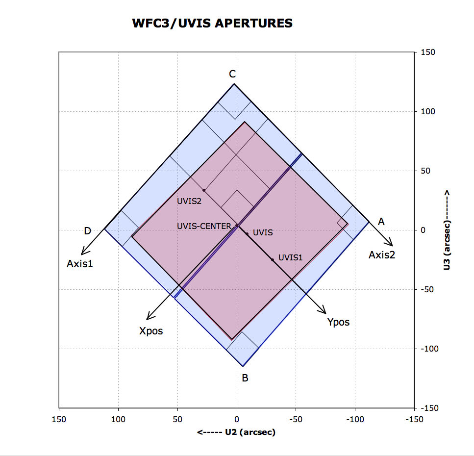
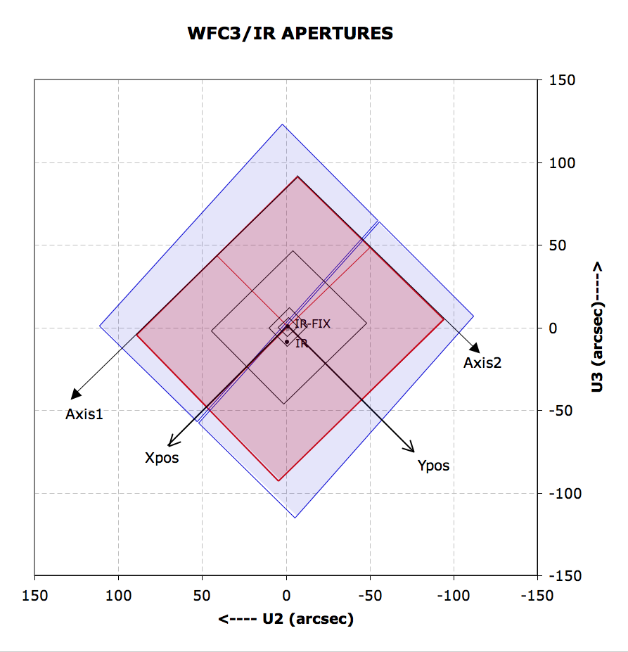
Figures 12.1 and 12.2 illustrate the locations of the UVIS and IR apertures. In the figures, the outlines of the full-detector apertures of both the UVIS and IR channels are indicated, as projected onto the sky and with respect to the HST U2-U3 coordinate system.

Figure 12.1: UVIS Aperture Diagram

Figure 12.1: UVIS Aperture Diagram illustrates the fiducial points of the full-detector apertures (UVIS, UVIS1, UVIS2, and UVIS-CENTER), and the outlines of the 2K × 2K, 1K × 1K, and 512 × 512 subarray apertures. Also indicated are the positions of the four readout amplifiers (A, B, C, and D). The regions imaged by the UVIS detector (represented by blue fill) and by the IR detector (represented by red fill) are also indicated. The POSition TARGet coordinate system for the UVIS-CENTER aperture, with its origin at that aperture's fiducial point, is illustrated. Although the POSition TARGet coordinate systems for the other apertures are not illustrated, they are oriented the same, but have origins at each aperture's fiducial point.
Figure 12.2: IR Aperture Diagram

Figure 12.2: IR Aperture Diagram illustrates the fiducial points of two of the full-detector apertures (IR and IR-FIX), and the outlines of the concentric subarray apertures (512 × 512, 256 × 256, 128 × 128, and 64 × 64). The regions imaged by the UVIS detector (represented by blue fill) and by the IR detector (represented by red fill) are also indicated. The POSition TARGet coordinate system for the IR-FIX Aperture, with its origin at that aperture's fiducial point, is illustrated. Although the POSition TARGet coordinate systems for the other apertures are not illustrated, they are oriented the same, but have origins at each aperture's fiducial point.


Table of Contents


Change Log

Version Cycle 32 May 2024

      PROPINST-91407- Improve the links to other documents.