7.1 STIS Patterns
Many HST STIS observations are obtained with some motion of the telescope (e.g., dithering, mosaicking), and there are predefined patterns available in APT to support these motions. |
On This Page
Format definitions
Boldface type indicates the name of an APT parameter or a value for a parameter.
![]() Black text indicates an important note.
Black text indicates an important note.
Magenta text indicates available but unsupported parameters (requires prior approval from STScI).
Red text indicates restricted parameters (for STScI use only).
Brown text indicates text file parameters.
Items in brackets - <value> - are required values.
Items in square brackets - [<value>] - are optional.
Introduction
There are 5 different predefined patterns that can be used with STIS, which are shown in Table 7.1: STIS Predefined Patterns. To see an illustration of the STIS POS-TARG reference frame, see 8.5.3 STIS Coordinate Systems.
Table 7.1: STIS Predefined Patterns
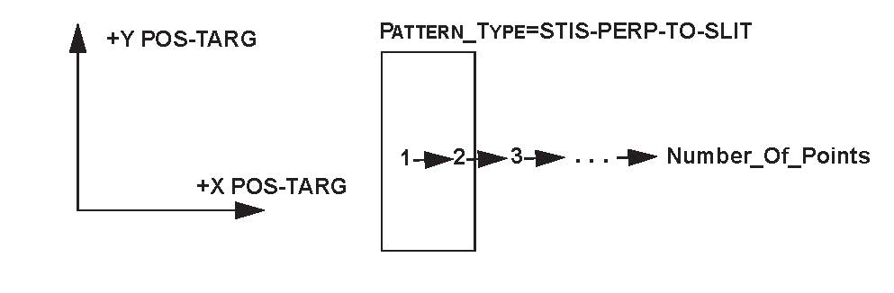
Pattern_Type: STIS-PERP-TO-SLIT
This is normally used with a spectroscopic slit. It produces a scan along the POS TARG X-axis of the aperture; this is used to map a two-dimensional region of the sky (see Chapter 11 of the STIS Instrument Handbook). The target is moved perpendicular to the slit along the AXIS1 (dispersion) direction.
Pattern_Type:STIS-PERP-TO-SLIT
Pattern_Purpose:MOSAIC
Number_of_Points:?
Point_Spacing:?
Coordinate_Frame:POS-TARG
Pattern_Orient:0
Center_Pattern:?
Permitted Sub-Pattern (Secondary_Pattern) values: STIS-ALONG-SLIT, LINE.
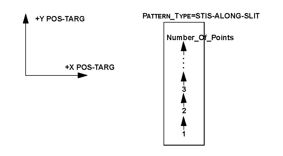
Pattern_Type: STIS-ALONG-SLIT
This is also normally used with a spectroscopic slit. It produces a scan along the POS TARG Y-axis of the aperture; this is used to step a target along the long slit to dither bad pixels or improve spatial resolution (see the STIS Instrument Handbook). The target is moved along the slit in the AXIS2 (cross-dispersion or spatial) direction.
Pattern_Type:STIS-ALONG-SLIT Pattern_Purpose:DITHER Number_of_Points:?Point_Spacing:? Coordinate_Frame:POS-TARG Pattern_Orient:90 Center_Pattern:?
Permitted Sub-Pattern (Secondary_Pattern) values: none.
To see an illustration of the STIS POS-TARG reference frame, see 8.5.3 STIS Coordinate Systems.
Pattern_Type: STIS-CCD-BOX
This will produce a four-point parallelogram scan designed for dithering across the CCD pixels. With the default Point_Spacing of 0.567, the four points of the parallelogram will be obtained at the following POS TARG (X,Y) offsets relative to the default aperture position:
(0.0", 0.0") (0.5070", 0.2535") (0.7605", 0.7605") (0.2535", 0.5070")
This default produces a parallelogram pattern (see diagram) with projected offsets from the starting point of 5n integer pixels in each coordinate, so that the above arcsec values correspond to pixel values of (0, 0), (10, 5), (15, 15), and (5, 10). With these integer-pixel offsets, the pattern is optimized to simultaneously compensate for hot pixels and small-scale detector non-uniformities. The pattern can be rescaled (e.g., by a factor of 0.5) to achieve shifts of N+half pixels for resolution enhancement by changing the Point_Spacing.
Pattern_Type:STIS-CCD-BOXPattern_Purpose:DITHERNumber_of_Points: 4Point_Spacing:0.0567-5.67 (default 0.567)Line_Spacing: Equal to Point_Spacing (may not be changed)Angle_Between_Sides:143.1 (may not be changed)Coordinate_Frame: POS-TARGPattern_Orient:? (default 26.6)Center_Pattern: ?
Permitted Sub-Pattern (Secondary_Pattern) values: none.
To see an illustration of the STIS POS-TARG reference frame, see 8.5.3 STIS Coordinate Systems.
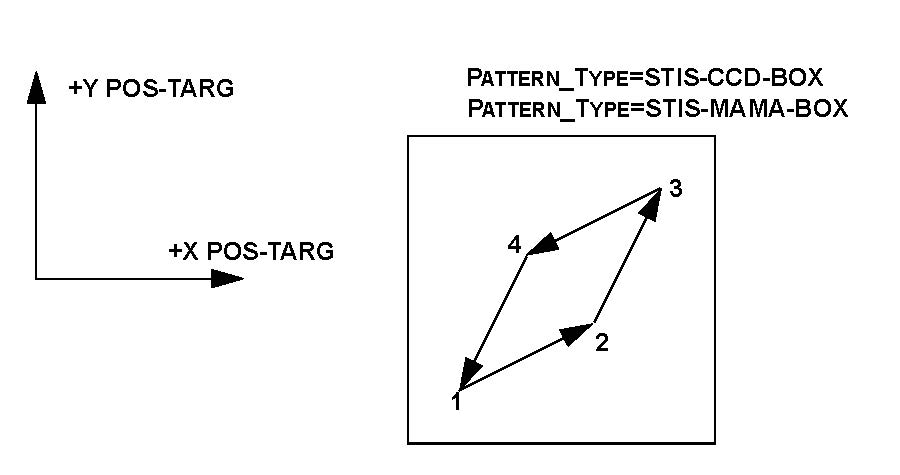
Pattern_Type: STIS-MAMA-BOX
This will produce a four-point parallelogram scan designed for dithering across the MAMA pixels. With the default Point_Spacing of 0.275, the four points of the parallelogram will be obtained at the following POS TARG (X,Y) offsets relative to the default aperture position:
(0.0", 0.0") (0.246", 0.123") (0.369", 0.369") (0.123", 0.246")
This default produces a parallelogram pattern (see diagram) with projected offsets from the starting point of 5n integer pixels in each coordinate, so that the above arcsec values correspond to pixel values of (0, 0), (10, 5), (15, 15), and (5, 10). With these integer-pixel offsets, the pattern is optimized to simultaneously compensate for hot pixels and small-scale detector non-uniformities. The pattern can be rescaled (e.g., by a factor of 0.5) to achieve shifts of N+half pixels for resolution enhancement by changing the Point_Spacing.
Pattern_Type:STIS-MAMA-BOX Pattern_Purpose:DITHER Number_of_Points:4Point_Spacing:0.0275-2.75 (default 0.275) Line_Spacing:Equal to Point_Spacing (may not be changed)Angle_Between_Sides:143.1 (may not be changed) Coordinate_Frame:POS-TARGPattern_Orient:? (default 26.6) Center_Pattern:?
Permitted Sub-Pattern (Secondary_Pattern) values: none.
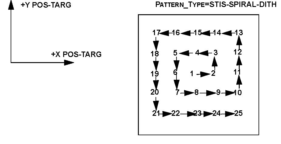
Pattern_Type: STIS-SPIRAL-DITH
This produces a spiral dither pattern, starting at the center and moving outward counterclockwise. Note that a STIS-SPIRAL-DITH with four points yields a square pattern, but the optimum pattern for detector dithering to enhance resolution is either STIS-CCD-BOX or STIS-MAMA-BOX.
Pattern_Type:STIS-SPIRAL-DITH Pattern_Purpose:DITHER Number_of_Points:?Point_Spacing:? Coordinate_Frame:POS-TARG Pattern_Orient:? (default 0) Center_Pattern:?
Permitted Sub-Pattern values: none.
To see an illustration of the STIS POS-TARG reference frame, see 8.5.3 STIS Coordinate Systems.
Related Links
7.2 ACS Patterns
7.3 WFC3 Patterns