2.1 The Optical Train
Each FGS comprises two orthogonal white-light, shearing interferometers, their associated optical and mechanical elements, and four S-20 photo-multiplier tubes (PMTs). For clarity, we divide the FGS optical train into two sections: Section 2.1.1 and Section 2.1.2.
2.1.1 The Star Selectors
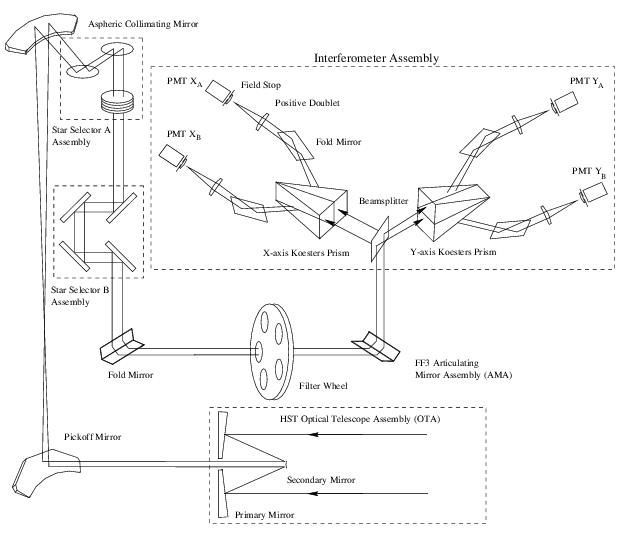
A schematic view of the FGS optical train is shown in Figure 2.1. Light from the HST Optical Telescope Assembly (OTA) is intercepted by a plane pickoff mirror in front of the HST focal plane and directed into the FGS. The beam is collimated and compressed (by a factor of ~60) by an aspheric collimating mirror, and guided to the optical elements of the Star Selector A (SSA) servo assembly. This assembly of two mirrors and a five element refractive corrector group can be commanded to rotate about the telescope’s optical axis. The corrector group compensates for designed optical aberrations induced by both the asphere and the HST Optical Telescope Assembly (OTA). The asphere contributes astigmatism, spherical aberration and coma to the incident beam. Aberrations from the OTA’s Ritchey-Chretien design include astigmatism and field curvature.
After the SSA assembly, the beam passes through a field stop (not shown) to minimize scattered light and narrow the field of view. The four mirrors of the Star Selector B (SSB) assembly intercept and re-direct the beam to a fold flat mirror and through the filter wheel assembly. From there, the Articulating Mirror Assembly (AMA) reflects the beam onto the Polarizing Beam Splitter. Like the SSA, the SSB assembly rotates about a vector parallel to the telescope’s optical axis. Together the SSA and SSB assemblies allow for the transmission to the polarizing beam splitter only those photons originating from a narrow region in the total FGS field of view. This area, called the Instantaneous Field of View (IFOV), is a 5 × 5 arcsec patch of sky, the position of which is uniquely determined by the rotation angles of both the SSA and SSB. The IFOV can be brought to any location in the full FOV and its position can be determined with sub-milliarcsecond precision (see Figure 1.3).
The AMA is an enhancement to the original FGS design. It allows for in-flight alignment of the collimated beam onto the polarizing beam splitter and therefore the Koesters prisms. Given HST’s spherically aberrated OTA, this is an important capability, the benefits of which will be discussed in subsequent chapters.
2.1.2 The Interferometer
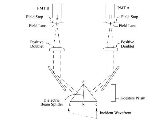
The interferometer consists of a polarizing beam splitter followed by two Koesters prisms. The polarizing beam splitter divides the incoming unpolarized light into two plane polarized beams with orthogonal polarizations, each having roughly half the incident intensity. The splitter then directs each beam to a Koesters prism and its associated optics, field stops, and photomultiplier tubes. Figure 2.2 illustrates the light path between the Koesters prism and the PMTs.
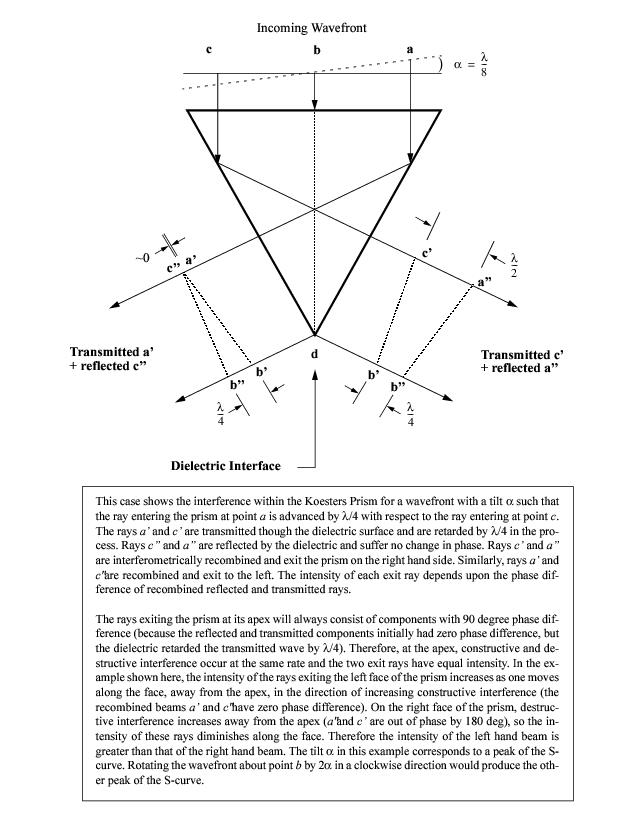
The Koesters prisms are constructed of two halves of fused silica joined together along a coated surface which acts as a dielectric beam splitter. The dielectric layer performs an equal intensity division of the beam, reflecting half and transmitting half, imparting a 90 degree phase lag in the transmitted beam. This division and phase shift gives the Koesters prism its interferometric properties: the beam reflected from one side of the prism interferes constructively or destructively with the beam transmitted from the other side. The degree of interference between the two beams is directly related to the angle, or tilt, between the incoming wavefront’s propagation vector and the plane of the dielectric surface.
Each Koesters prism emits two exit beams whose relative intensities depend on the tilt of the incident wavefront. Each beam is focussed by a positive doublet onto a field stop assembly (which narrows the IFOV to 5 × 5 arcsec). The focussed beams are recollimated by field lenses (after the field stop) and illuminate the photomultiplier tubes (PMT). The PMT electronics integrate the photon counts over 25 millisecond intervals.
The Koesters prism is sensitive to the angle of the incoming wavefront as projected onto its dielectric surface. To measure the true (non-projected) direction of the source, each FGS has two Koesters prisms oriented perpendicular to one another (and therefore a total of 4 PMTs).


