6.3.1 General Exposure-level Special Requirements
General Exposure-level Special Requirements (e.g., SPATIAL SCAN, PARALLEL) are generally used to specify special properties of HST exposures. The Astronomer's Proposal Tool (APT) is used to enter the requirements into the proposal. |
On This Page
Format definitions
Boldface type indicates the name of an APT parameter or a value for a parameter.
![]() Black text indicates an important note.
Black text indicates an important note.
Magenta text indicates available but unsupported parameters (requires prior approval from STScI).
Red text indicates restricted parameters (for STScI use only).
Brown text indicates text file parameters.
Items in brackets - <value> - are required values.
Items in square brackets - [<value>] - are optional.
Introduction
Most General Exposure-level Special Requirements are used to specify special properties of HST exposures (as opposed to affecting scheduling). Special requirements should not be used unless necessary to accomplish the scientific objectives of the proposal.
Target Acquisition
Separate target acquisition exposures must be specified at the beginning of most visits, depending on the target and the science instrument used. Target acquisition exposures are used to remove coordinate uncertainties and to identify targets. Once a target acquisition has been performed, HST can move the target from aperture to aperture or move the aperture around the target (with slew accuracies of about 10 milliarcseconds) as long as the same guide stars can be used. Onboard acquisitions are automatically identified by the software. Acquisition exposures must still be specified, but no Special Requirement is needed or appropriate.
Acquisition of a target using an offset target requires that both be defined in the Target List(s). The first exposure will be an onboard or interactive acquisition of a target from which the offset will be made. This target must be designated as an offset acquisition target by appending -OFFSET to the end of the target name (see Table 3.1: Designations of Special Targets). The appropriate offsets will automatically be made from this position to slew to the target of interest.
INTeractive ACQuisition (obsolete)
|
Interactive acquisitions may no longer be performed with HST. However, the same results can be achieved in other ways, and you should consult your Program Coordinator for more information.
For available but unsupported parameters (SAVE OFFSET, USE OFFSET)
SAVE OFFSET <id>
This requirement is used to save the results of a target acquisition sequence for use by one or more subsequent exposures, which are normally in different visits. SAVE OFFSET indicates that this exposure will generate a pointing correction (or “offset”) for future science exposures which specify USE OFFSET with the same <id>.
The purpose of the SAVE OFFSET/USE OFFSET procedure is to allow more efficient and flexible scheduling of observations. This Special Requirement is especially useful for replacing INTeractive ACQuisitions, which are no longer supported. Unlike the former INTeractive ACQuisition Special Requirement, the SAVE OFFSET/USE OFFSET procedure is not considered a limited resource. It should be used whenever it is possible to leave at least 3 days between this exposure and the first science exposure which uses the acquisition (in some instances this time delay can be reduced to as little as three orbits).
Target acquisition time may be saved if repeated observations of the same target are planned for multiple visits. In the first visit, the relevant target acquisition exposure should include the SAVE OFFSET <id> Special Requirement. Subsequent visits to the same target do not require repeating the target acquisition procedure; these exposures can simply specify the USE OFFSET <id> Special Requirement.
In either case, unless the RT ANALYSIS Special Requirement is placed on the same exposure, visits which use an offset will be scheduled at least 3 days after the initial SAVE OFFSET visit. This allows time for the data to be downlinked and analyzed. The offset may not be saved and used in the same visit. For exposures with modes beginning with “ACQ,” visits which use an offset will be scheduled at least 3 days after the initial SAVE OFFSET visit.
The <id> is an alphanumeric string of up to six characters in length. No two SAVE OFFSET Special Requirements in a proposal may use the same <id>, and every <id> from a SAVE OFFSET exposure must be used in at least one USE OFFSET exposure.
|
USE OFFSET <id>
This Special Requirement is used to apply the results of a previous target acquisition sequence (one that specified SAVE OFFSET with the same <id>). Only one USE OFFSET Special Requirement is allowed per exposure, but it is permissible to use multiple offset <id>’s in the same visit. STScI personnel will help determine the necessary offsets. These offsets may require a minute or two of orbital visibility time.
As described under SAVE OFFSET, this Special Requirement is useful for replacing the former INTeractive ACQuisition. The observer is usually required to be present at STScI at the time the SAVE OFFSET exposure is taken to determine the offset. Please contact your Program Coordinator.
Unless the SAVE OFFSET exposure also has the RT ANALYSIS Special Requirement, the SAVE OFFSET and USE OFFSET exposures must be in separate visits, and the visits will be scheduled at least 3 days apart. If the SAVE OFFSET exposure uses a mode beginning with “ACQ,” visits using an offset will be scheduled at least 3 days after the initial SAVE OFFSET visit. It is not possible to override this separation with an AFTER Special Requirement. The SAME ORIENTation Special Requirement is implicit and need not be specified directly. See the discussion on target orientation for an explanation of the restrictions this places on how far apart the visits may be scheduled.
If the exposure is on a moving target, the maximum target acquisition uncertainty must be specified in the solar-system target list (see Acquisition Uncertainty). If the exposure is on a fixed target, the position uncertainty in the fixed target list (see Required Accuracies of Target Positions) is used to determine the maximum offset. STScI will be unable to schedule corrections larger than this maximum offset, so too small an uncertainty may limit the usefulness of the USE OFFSET procedure. However, offsets larger than about 1 arcminute may make scheduling difficult. If your observation requires a correction this large, contact your Program Coordinator.
The <id> is an alphanumeric string of up to six characters in length, and must be identical to the <id> defined by the preceding exposure with the SAVE OFFSET Special Requirement. Note that the <id> need only be unique within the proposal. It is not possible to use offsets across multiple proposals.
For restricted parameters (USE OFFSET)
Special Observation Requirements
SPATIAL SCAN <Scan_Rate>, <Scan_Orient>, <Scan_Direction>, <Scan_Line_Separation>, <Scan_Number_Lines>
HST has the capability of performing a single and multi line continuous (serpentine) scans relative to the target. Such scans may be useful for observing very bright targets without sacrificing visibility to serial buffer dumps, for example.
Spatial Scans are obtained by moving the spacecraft in a way that moves the target in the instrument aperture along a path in the POS TARG coordinate frame (see POSition TARGet <X-value>,<Y-value>) as designated by the observer. The scan is defined relative to the aperture fiducial point within the SI aperture.
Only one exposure may be executed during a spatial scan, and only one spatial scan may be executed during an exposure. STScI will schedule a spatial scan so that the constant rate portion of the first scan begins at the start of the exposure and the constant rate portion of the last scan ends at the end of the exposure.
Table 6.4: Spatial Scan Parameters1
| Parameter | Description | Allowed Values | Required |
|---|---|---|---|
| Scan_Rate (arcsec/sec) | The constant angular rate at which the target will move with respect to the POS TARG coordinate frame. | 0.0 to 0.999999 arcsec/sec for multi-line scans under FGS control. 0.0 to 4.999999 arcsec/sec for single-line scans under FGS control. | Yes |
| Scan_Orient (Degrees) | The orientation of the scan line with respect to the POS TARG coordinate frame. It is measured from the POS TARG +X-axis toward the +Y-axis. | 0 to 360° | Yes |
| Scan_Direction | The "direction" of the scan. | "Forward", "Reverse" and "RoundTrip"2 | Yes |
| Scan_Line_Separation (arcsec) | The separation between the adjacent scan lines in arcseconds. The total width of the scan can be found by Scan_Width = Scan_Line_Separation × (Scan_Number_Lines - 1) | 0.0 arcsec for all single line scans. For multi-line scans:
| Yes |
| Scan_Number_Lines | The number of scan lines to perform. | 1 to 63 lines | Yes |
1 See also General Considerations for Spatial Scans. Note that only multi-line "Forward" spatial scans are supported.
2 A "Forward" scan will start at the aperture fiducial point (nominal target position; see point a in Figure 6.8: "Forward" Spatial Scan) and proceed to the end of the scan (point b in Figure 6.8: "Forward" Spatial Scan). A "Reverse" scan will run opposite to the corresponding "Forward" one, with it ending at the aperture fiducial point (i.e., from point b to point a in Figure 6.9: "Reverse" Spatial Scan) and is also subject to consideration 9 below. A "RoundTrip" scan will be performed as two scans: a "Forward" scan followed by a "Reverse" scan with identical setup parameters.
General Considerations for Spatial Scans
- The allowed combinations are ACS/WFC ACCUM, STIS/CCD ACCUM, WFC3/IR MULTIACCUM and WFC3/UVIS ACCUM.
- The maximum Scan_Rate is 4.999999 arcsec/sec under FGS control. Faster scans under Gyro control are no longer possible in RGM.
- The SI Optional Parameter CR-SPLIT must be NO via default or an explicit specification.
- The angular length of a scan will be determined from the total exposure time (including some overheads in the case of WFC3/IR), the Scan_Rate, the Scan_Line_Separation and the Scan_Number_Lines. For multi-line scans, the total exposure time encompasses all of the scan lines plus the turn around maneuvers between the lines. It is your responsibility to ensure that the scan does not extend off the detector unless necessary to accomplish the goals of the observation.
- Only Multi-line "Forward" spatial scans are supported.
- The turnaround maneuver time is computed in two parts and then combined
- The time to ramp-up/ramp-down each scan line: Ramp-up_Time = max(sqrt(100 * Scan_Rate), 5) seconds
- The time for the transverse move from one scan line to the next: If Scan_Line_Separation ≤ 10 arcsec then Transverse_Time = max((800 * Scan_Line_Separation)**(1/3), 10) seconds else Transverse_Time = (Scan_Line_Separation + 10) seconds.
- Then we combine the Ramp-up_Time and the Transverse_Time to determine the time for each turnaround maneuver:
Turnaround_Time = max(2 * Ramp-up_Time, Transverse_Time) seconds.
Be sure to round to the next higher integer before using it to determine your exposure time.
- During a scan the telescope moves. Consequently, for a scan under FGS control, the guide stars will move within the fields of view of the FGS being used. It is essential that none of the guide stars moves out of the field of view of its FGS. Therefore, requesting a scan under FGS control imposes additional selection requirements on the available guide stars, which will effectively reduce the number of stars that can be used for the observation. The degree of this reduction will depend on the length of the scan relative to the width of the FGS fields of view (4 arcmin). If the size of the scan precludes finding good guide stars, the observation will not be schedulable (unless a single guide star can be found by the PCs).
- The entire scan must complete during a single target visibility period. "RoundTrip" scans are expanded into individual "Forward" and "Reverse" scans. As a result, those individual scans may be split between different target visibilities unless the "RoundTrip" exposure is within a SEQ NON-INT container.
- The scan specifications in Spatial Scan Parameters apply to the aperture fiducial point in the SI aperture for the exposure unless you use a POSition TARGet <X-value>,<Y-value> or PATTERN special requirement. When you use POS TARG, the scan is performed relative to the point defined by the POS TARG. When you use PATTERN, the scan will be performed for each exposure of the PATTERN relative to its pattern point.
- Scans are not permitted for exposures with Moving Targets.
- Scans are not permitted for exposures with Internal Targets.
- Special Requirement SAME POSition AS <exposure> is not permitted on and can not refer to a Spatial Scan exposure.
- Spatial Scan exposures are not permitted in Coordinated Parallel Containers (Special Requirement PARallel WITH is not permitted on and can not refer to a Spatial Scan exposure).
- Spatial Scan exposures are not permitted in Pure Parallel visits. Pure Parallel visits may not be in parallel with Spatial Scan exposures.
- The Spatial Scan parameters describe the desired scan in the POSition TARGet <X-value>,<Y-value> coordinate frame. You may need to adjust the Scan_Orient appropriately to account for the geometric distortion of the detector. You may also have to adjust the Scan_Rate, which is arcsec/sec in the POS TARG frame, to account for the geometric distortion of the detector if you need a particular pixel traverse rate.
- Since a multi-line scan is executed as a single exposure, the turnaround part of the scan may be imaged on the detector. This turnaround will not occur at constant velocity or at constant rate. If this is not desired, then a series of single-line scans should be used instead. See Figure 6.10: Multi-line "Forward" Spatial Scan.
We advise observers that neither the CALWF3 pipeline nor generic analysis software is designed to calibrate spatially scanned ACS, STIS or WFC3 data and you should plan accordingly.
Figure 6.8: "Forward" Spatial Scan
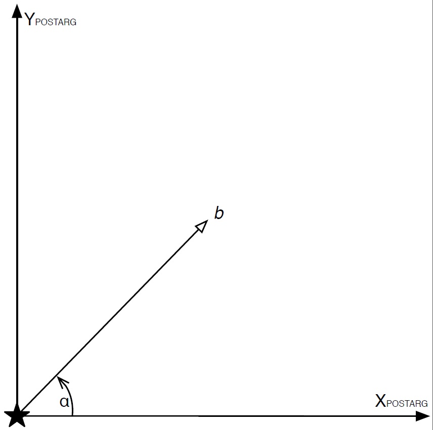
The figure shows a single-line "Forward" scan from point a to point b at a Scan_Orient angle α with the target at the aperture fiducial point at the start of the scan.
Figure 6.9: "Reverse" Spatial Scan
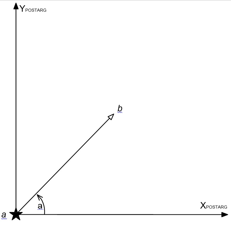
The figure shows a "Reverse" scan starting with the target at point b, moving at Scan_Orient angle α, and ending with the target at the aperture fiducial point (point a).
Figure 6.10: Multi-line "Forward" Spatial Scan
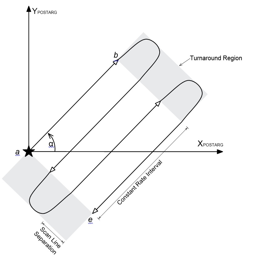
The figure shows a multi-line "Forward" scan where the exposure will start with the target at point a and ends with the target at point e. Note that the turnaround portions take place during the exposure and may be imaged by the detector. If this is not desired, then a series of single-line scans should be used instead.
PARallel <parallel-exp-list> WITH <primary-exp-list>
This special requirement specifies that the exposures in <parallel-exp-list> will execute in parallel with a sequence of exposures in <primary-exp-list>. In the Text Proposal File, both <primary-exp-list> and <parallel-exp-list> must be replaced by either a single exposure number, or a range of exposure numbers separated by a hyphen. See Coordinated Parallel Containers for more details. (This Special Requirement must have been indicated in the Phase 1 proposal.)
For available but unsupported parameters (SAA CONTOUR, QASISTATES, QESIPARM, QELOGSHEET)
SAA CONTOUR <model number>
(available but unsupported for WFC3, ACS/WFC and S/C modes; restricted for ACS/SBC, CAL and ENG proposals)
Specifies the contour of the South Atlantic Anomaly (SAA) to be used for scheduling this exposure. If this requirement is not provided, a default SAA contour appropriate to the SI will be assigned (see table below). Use of less a restrictive model may improve the schedulability of observations that can tolerate higher radiation levels. The following model numbers are allowed (ordered from most to least restrictive).
| SAA Model | Instrument for which model is default |
|---|---|
| 05 | FGS Astrometry |
| 29 | WFC3/UVIS |
| 30 | WFC3/IR |
| 27 | ACS/WFC |
| 28 | ACS/SBC |
| 24 | STIS/CCD |
| 25 | STIS/MAMA |
| 31 | COS/FUV |
| 32 | COS/NUV |
| 02 | FGS Guiding |
| 11 | no avoidance |
The SAA contours in use in August 2014 are displayed in Figure 6.11: SAA contours for the HST instruments. Older definitions of the contours are shown at:
http://www.sesd.stsci.edu/et/seu/seu.html
Figure 6.11: SAA contours for the HST instruments
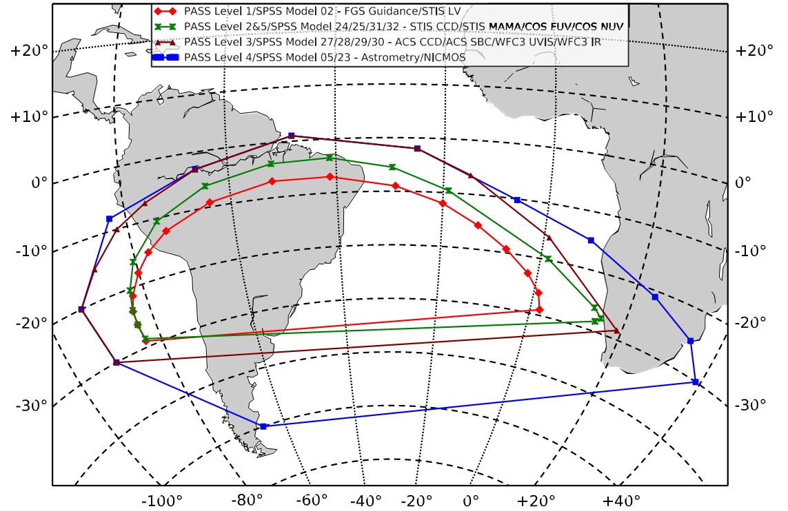
02 is the minimal FGS contour needed to avoid radiation at levels that would interfere with guide star lock. The default contours vary by SI but are more restrictive (meaning lower maximum radiation levels and longer SAA interruption times) than the 02 contour for all instruments.
A value of 11 means the SAA constraint will be ignored entirely. This requires a drop to gyro control for the exposure (also see the discussions under PCS MODE Fine, PCS MODE Gyro, and DROP TO GYRO [NO REACQuisition]), even if the visit as a whole is done under FGS control.
QASISTATES <si> <detector> <start> <end>
QESIPARM <parameter> <value>
QELOGSHEET <parameter> <value>
For restricted parameters (Spec Comm)
Special Communications Requirements
RT ANALYSIS
Specifies that the current science exposure must be made available to the observer for analysis in real time. Any science exposures whose execution depends upon a decision based on the real-time analysis should have RT ANALYSIS specified. The REQuires UPLINK Special Requirement may also be used with RT ANALYSIS to establish the ground-to-spacecraft link. The current exposure will be available for analysis at least 16 minutes (for fixed targets) prior to that uplink; for moving targets the time is 24 minutes.
This Special Requirement is a limited resource and should only be used when necessary (please consult with your PC prior to using this mode). Justification for its necessity should be included in the Real_Time_Justification text.
Note that the exposures in the <exposure-list> must be in the same visit as the current exposure, and RT ANALYSIS may not be used if the exposure uses patterns or if Number_of_Iterations > 1.
REQuires UPLINK
Indicates that a real-time command uplink is needed to execute this exposure. An uplink will be scheduled prior to the current exposure. This Special Requirement should be used with RT ANALYSIS to replace the capability formerly available with INTeractive ACQuisition (obsolete) and it should specifically identify which exposures need an uplink, assuming that the uplink already provided is not sufficient. This Special Requirement can also be used without RT ANALYSIS if the information which needs to be uplinked is not dependent on real-time analysis of HST data. Usage of this Special Requirement is considered a limited resource and should only be used when necessary. Justification for its necessity should be included in the Real_Time_Justification text.
REQuires EPHEMeris CORRection <id>
Indicates that a correction for position errors due to moving-target and/or HST ephemeris uncertainty may be needed to execute the exposure. This Special Requirement is only valid for exposures with moving targets. The offset will be uplinked during an available (“generic”) uplink prior to the earliest exposure that uses it. The pointing correction may require a minute or two of orbital visibility time.
An ephemeris correction is needed in two cases:
- When observing an object within about 1 AU of the Earth. In this case, the uncertainty in the position of HST accumulated between the time the schedule is built and the time it is executed can cause the observation to miss the target. (The HST ephemeris is inaccurate by as much as 60 seconds, which translates into a positional error on the moving target). The offset can be easily calculated by STScI personnel in this case.
- When observing an object with an uncertain ephemeris. In this case, updated positions may be used until shortly before the observation actually executes, even though the elements in the program are out of date. Again, STScI personnel can easily determine the proper offset.
With moving targets, the maximum target ephemeris uncertainty must be specified in the solar-system target list (see 3.2 Solar System Targets. STScI will be unable to schedule corrections larger than the maximum offset derived from this uncertainty, so too small an uncertainty may limit the usefulness of the REQ EPHEM CORR procedure. However, offsets larger than about 1 arcminute may make scheduling difficult. If your observation requires a correction this large, contact your Program Coordinator.
The <id> is an alphanumeric string of up to six characters in length. Exposures with the same REQ EPHEM CORR ID (whether in the same visit or in different visits) will use the same offset and must be taken at the same orientation. If exposures in different visits use the same ID, the visits involved are all subject to the same scheduling restrictions as SAME ORIENTation AS <visit>. The SAME ORIENT Special Requirement is implied across such a set of visits, and need not be specified directly.
For engineering parameters (FORMAT)
FORMAT [AN or FN or HN or PN]
Engineering telemetry of the specified format will be obtained during an exposure. If FORMAT is specified, a legal value must be used. There is no default value for FORMAT.
Format can be used only for FGS and S/C DATA mode exposures.
|
|---|
Related Links
6.3.2 Timing Exposure-level Special Requirements
6.3.3 Target Position Exposure-level Special Requirements