6.2.2 Target Orientation Visit-level Special Requirements
General Special Requirements (e.g., GUIDING, CVZ) are generally used to restrict the scheduling of HST observations by various constraints. The Astronomer's Proposal Tool (APT) is used to enter the requirements into the proposal. |
On This Page
Introduction
Most general special requirements directly or indirectly restrict the times when observations (and/or their component visits) can be scheduled. These should be used to provide the schedulers at STScI with enough constraints to ensure that the observations are properly scheduled. Special requirements should not be used unless necessary to accomplish the scientific objectives of the proposal.
The solar arrays of HST must be kept pointed at the Sun (to within a modest angle) in order for the spacecraft to have the electrical power it needs. As the Sun moves through the heavens over the course of a year, this requirement for the solar arrays translates into a position angle on the sky on which HST’s detectors lie. Therefore an observer-imposed requirement to, say, orient a slit in a particular position angle means that observation must be done at a specific time. When a special aperture orientation is requested, this will generally be accommodated by scheduling the observation during the time interval when that orientation naturally results in the solar array being positioned nearly perpendicular to the Sun (this is called the “nominal” orientation).
In order to achieve a specific orientation and satisfy spacecraft roll constraints, an observation generally must be scheduled within a fairly narrow time interval. The placement and duration of time intervals that satisfy this constraint will depend on the ecliptic coordinates of the target. The observer must take this into consideration when specifying additional timing constraints (e.g., BETWEEN, BEFORE, AFTER). For a discussion of nominal roll and how it changes with time based on ecliptic latitude, see the section on Nominal and Off-Nominal Roll below.
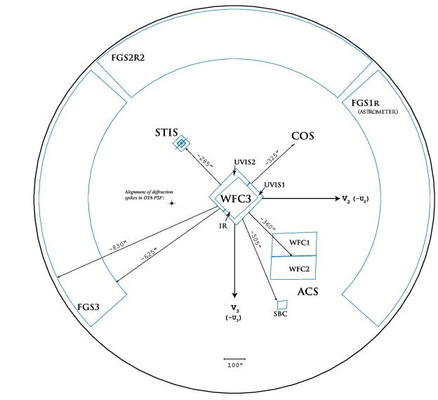
The placement of the instruments in the HST coordinate system is shown in the Field of View (FOV).
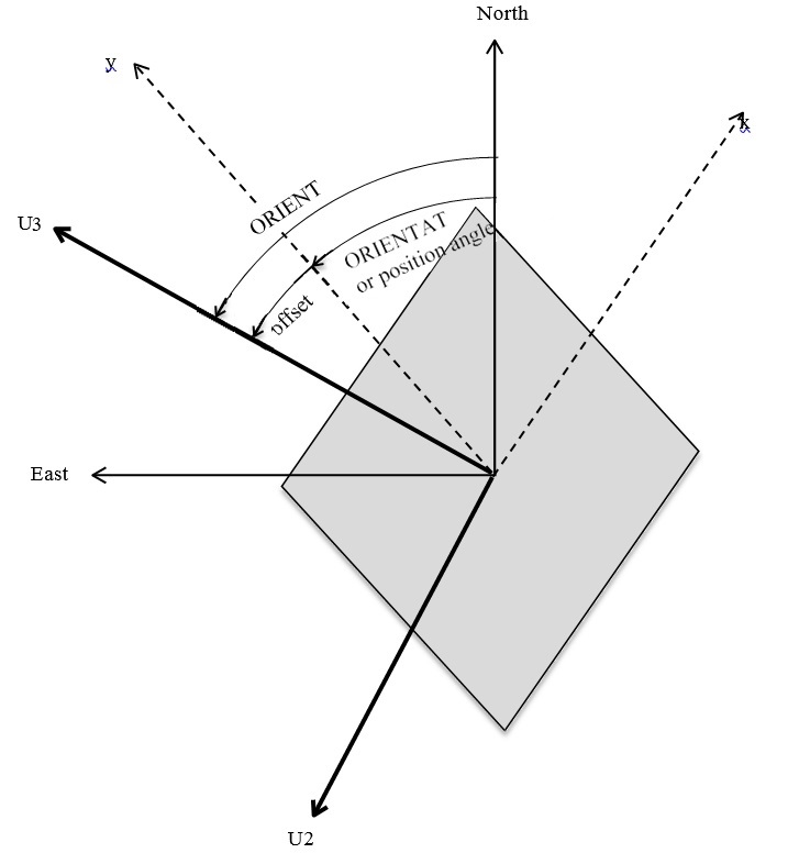
Observers can constrain the orientation of the instrument(s) on the sky during a visit by specifying the position angle of the HST reference vector U3; i.e., by specifying the rotation from North towards East to this U3 axis direction. To constrain the orientation of an axis of an aperture, a slit, an aperture pair, etc., we therefore need to know how this selected axis is oriented with respect to U3. Table 6.3: Approximate Separation and Orientations between the Science Instruments provides this information, i.e., the angle measured from the selected axis direction to U3, which we will call the offset angle. To obtain the North to U3 angle, ORIENT, the observer should add the offset angle for the selected axis and the desired position angle on the sky of the selected axis:
ORIENT = offset angle(selected axis) + PAaxis
If the selected axis is the y axis of the aperture, this becomes
ORIENT = offset angle(y axis) + PA(y axis) = offset angle(y axis) + ORIENTAT
where ORIENTAT is defined as the position angle of the y axis of the aperture (and will appear in the science header), and offset angle(y axis) is, for example, 135° for WFC3/UVIS apertures (Table 6.2: Accuracies of Guiding Modes).
The above equation can be used to select values of ORIENT to avoid. As explained in Table 6.2: Accuracies of Guiding Modes, the Y axis of a WFC3/UVIS aperture is aligned with the columns of the CCD chip. Saturated pixels bleed flux along columns. (See WFC3 ISR 2010-10.) If the position angle of the Y axis, PA(y axis), coincides with the position angle of the vector from the target to a badly saturated star, PA(star), flux from the saturated core of the star will bleed towards the target along columns. For a star due north of a target (PA(star) = 0), one should avoid using ORIENT = 135 + 0 = 135 degrees if the bleeding flux may reach the target. Bleeding occurs in both directions along the columns, so ORIENT = 135 + 180 = 315 degrees should also be avoided. For a star at position angle N degrees, avoid ORIENT = 135 + N degrees and also ORIENT = 135 + N + 180 degrees. To allow for geometric distortion and errors in the angles, create an avoidance zone by adding a buffer of +/-10° to these ORIENTs. (A wider buffer zone may unnecessarily limit scheduling opportunities.) Thus, in summary, specify ORIENT ranges such that (ORIENT - PA(y axis)) = (ORIENT - PA(star)) is not within +/-10° of 135° and 315°.
If the target is faint, one may need to avoid placing it on the diffraction spikes from a bright star, which are oriented at about 45° from the columns on the WFC3/UVIS detector. (See WFC3 ISR 2011-03.) Therefore, avoid (ORIENT - PA(y axis)) = 45° from 135° and 315° (from above), so avoid (ORIENT - PA(y axis)) = 0°, 90°, 180°, and 270°. As above, create an avoidance zone by adding a buffer of +/-10°. The WFC3/IR detector has the same offset angle as the WFC3/UVIS detector (see Table 6.2: Accuracies of Guiding Modes), and uses the same Y axis convention (the Y axis is aligned with columns), so the same numbers apply to the WFC3/IR detector.
Instrument Orientation Tables
Table 6.2: Accuracies of Guiding Modes
For more information refer to http://www.stsci.edu/hst/instrumentation/focus-and-pointing/apertures
| Instrument | Item | Offset Angle1 | Comments |
|---|---|---|---|
FGS (see Figure 9.1: The FGS TARG and Interfermometer Coordinate Systems) | +X axis for FGS1 | 180° | |
+X axis for FGS2 | 90° | ||
+X axis for FGS3 | 0° | ||
STIS (see Figure 8.1: STIS Coordinate System) | All configurations: | Nominal, +/- 4° | |
Long Slit Spatial/+AXIS2/+Y | 45° | ||
Dispersion/+AXIS1/+X | 135° | ||
Toward increasing occultation: | |||
WEDGEA | 45° | ||
WEDGEB | 135° | ||
WFC3 (see Figure 12.1: UVIS Aperture Diagram and Figure 12.2: IR Aperture Diagram) | UVIS +Y (UVIS CCD column, same as the Y_POSTARG direction) | 135° | |
IR +Y | 135° | ||
UVIS +X (UVIS CCD row) | 221° | ||
IR +X | 224° | ||
COS (see Figure 11.1: COS Aperture Coordinate System ) | FUV +Y (spatial axis) | 135° | |
NUV +Y (spatial axis) | 135° | ||
FUV +X (dispersion axis) | 45° | ||
NUV +X (dispersion axis) | 45° | ||
ACS (see Figure 10.1: ACS Coordinate System) | WFC1 + Y axis | 2° | |
| WFC2 + Y axis | 2° | ||
| SBC + Y axis | 180° | ||
| WFCENTER + Y axis | 2° | ||
| WFCENTER + Y axis | 2° | ||
For available but unsupported parameters (STIS)
1 The Offset Angle is the angle from the axis defined in the Item column to the +U3 axis in the counterclockwise (or +U3 through +U2) direction. To compute the angle needed in the ORIENT Special Requirement, add this Offset Angle in column 3 to the Sky Position Angle (measured North through East). These angles are calculated from current alignment calibrations and reflect uncertainties of +/- 1°, except where greater uncertainties are indicated in the table comments. For the best estimate of an error for a specific SI, which is usually much less than 1°, consult with the SI team or go to the SI web pages available at: http://www.stsci.edu/hst/instrumentation.
Figure 6.2: Relationship between ORIENT, offset angle, and position angle shows the relationship between these angles in the case that the selected axis is the y axis of the aperture, but can be generalized to other cases as described below the figure. The projection of the aperture on the sky may be skewed, as shown in the figure.
Table 6.2: Accuracies of Guiding Modes gives offset angles to an accuracy of +/- 1° for each instrument (or larger if indicated in the Comments column). These should be adequate for most purposes. There are differences of fractional degrees between the offset angles of different apertures on the same instrument because the angles are measured locally at the fiducial point of each aperture. The most accurate offset angles for the x and y axes for each aperture on each instrument may be found under http://www.stsci.edu/hst/instrumentation/focus-and-pointing/apertures
These angles are in the V2,V3 system, which is rotated by exactly 180° from the U2,U3 system, and are measured in the opposite sense, i.e. from V3 to the axis. So before doing the above calculation, subtract these tabulated axis angles from 180°. For example, to assign the offset angle for the UVIS-FIX y axis, read the V3 to Y axis angle, which is 44.8°, and subtract this from 180° to get 135.2° (compared to 135° from Table 6.2: Accuracies of Guiding Modes). Similarly, the UVIS-FIX x axis is -41.4° from V3, leading to a U3 offset angle of 221.4° (compared to 221° from Table 6.2: Accuracies of Guiding Modes).
As another example, suppose that an observer determines that ORIENTAT=30.0° is the optimal orientation of the WFC3/IR GRISM1024 aperture to avoid the overlap of G141 spectra in a moderately dense field (see Section 8.3 of the WFC3 Instrument Handbook). In this case, offset angle(y axis) = 180.0 – 44.7 = 135.3° (compared to 135° from Table 6.3: Approximate Separation and Orientations between the Science Instruments), so ORIENT = 135.3 + 30.0 = 165.3°. Note that the skew of the projected aperture on the sky is very small (44.7-(-45.2)=89.9~90°).
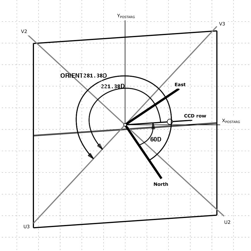
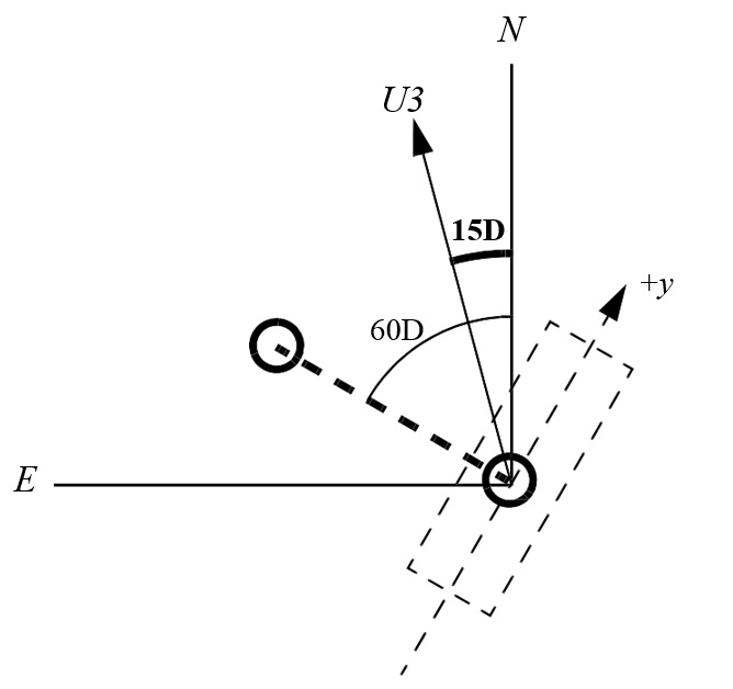
Further examples of computing the ORIENT of a visit are illustrated in Figures 6.3, 6.4, 6.5, and 6.6.
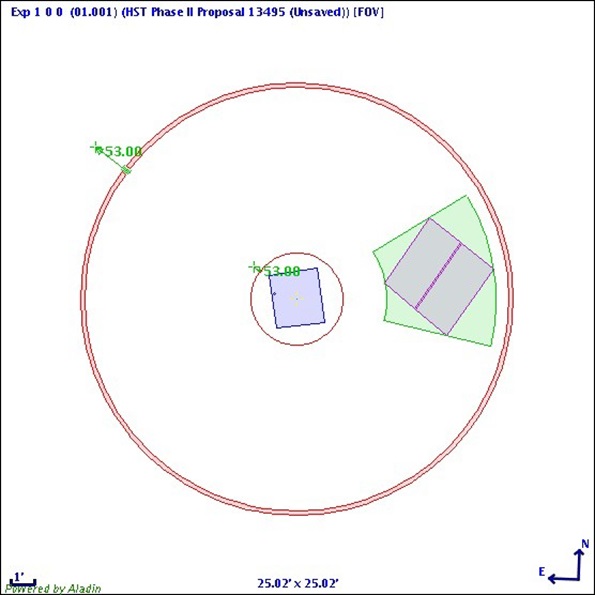
To control the placement of two instruments on an astronomical field in coordinated parallel exposures, one can make use of the angle between the U3 axis and the line connecting the centers of the two instruments, as specified and described in Table 6.3: Approximate Separation and Orientations between the Science Instruments). For example, for some of the visits in the Frontier Fields programs that use aperture WFCENTER on ACS/WFC in parallel to aperture IR-FIX on WFC3/IR:
ORIENT=offset(WFC3 to ACS/WFC)+PAaxis (axis = vector from WFC3 to ACS/WFC)
The desired PAaxis was 280°. From Table 6.3: Approximate Separation and Orientations between the Science Instruments, the offset angle (WFC3 TO ACS/WFC) is 133°, so ORIENT = 133 + 280 = 413° = 53°. The placement of the apertures on the sky is shown in Figure 6.6: Orientation computation for ACS/WFC.
Table 6.3: Approximate Separation and Orientations between the Science Instruments
1 The vector separations are calculated from current estimates of the locations of the WFC3, COS, and STIS apertures. These values can change with time.
2 The Offset Angle is defined as the angle from the line connecting the two Science Instruments to the +U3 axis in the counterclockwise direction (the +U3 through +U2 direction). These numbers are calculated from current estimates and reflect uncertainties of +/- 1°, except where greater uncertainties are indicated in the table.
|
Specifying ORIENT
The value or range of values of ORIENT required for a visit should be specified in the Special Requirement ORIENTation <angle1> TO <angle2> or, to relate the ORIENT of one visit to that of another visit, ORIENTation <angle1> TO <angle2> FROM <visit> or SAME ORIENTation AS <visit>. Each of these Special Requirements is discussed below. If there is any uncertainty in specifying an orientation, please document the calculations in the Visit_Comments and contact your Program Coordinator for clarification.
If a visit contains multiple targets requiring different guide stars, the spacecraft orientation will normally be reset to the “nominal” orientation each time a new set of guide stars is acquired. However, if the visit has Special Requirement ORIENTation <angle1> TO <angle2> FROM <visit> or SAME ORIENTation AS <visit>, the spacecraft orientation will not change during the visit, even if multiple sets of guide stars are needed.
ORIENTation <angle1> TO <angle2>
Specifies that a specific absolute roll angle or orientation of the spacecraft is required for the exposures within the current visit. <angle1> and <angle2> denote a region within which the position of the U3 axis on the sky (measured North through East) must fall at the time of the observation; both limits must be between 0° (0°) and 360° (360°). If necessary, it is possible for <angle1> and <angle2> to be equal, but the size of the region between the two limits should be made as large as possible to make scheduling easier. Note that in most instances the angles can have a 180° offset and still work. If this is desired (for greater scheduling flexibility), please specify the additional possible angles. (This Special Requirement must have been indicated in the Phase 1 proposal.)
Note also that this Special Requirement can list several acceptable angle ranges:
ORIENTation <angle1> TO <angle2>
ORIENTation <angle3> TO <angle4>
ORIENTation <angle5> TO <angle6>
ORIENTation <angle7> TO <angle8> . . .
Both angles are measured in a counterclockwise direction, so if the orientation region crosses zero (celestial North), <angle1> would be greater than <angle2>. Otherwise, <angle1> should be less than <angle2>. It is also possible for the orientation region to be larger than 180°. You are encouraged to enter both the aperture angle(s) and the offset angle used to calculate these angles in the Visit_Comments.
Note: If the visit uses multiple targets, the direction of North from the first target will be used. The spacecraft will not roll between targets, so that the U3 position angle at the new target may be slightly different from that of the first target.
ORIENTation <angle1> TO <angle2> FROM <visit>
Specifies that a roll angle or orientation of the spacecraft, relative to another visit’s spacecraft orientation, is required for the exposures within the current visit. <angle1> and <angle2> denote a region of permitted orientation of the current visit relative to <visit>. <angle1> and <angle2> must be between -180° (-180°) and +180° (180°). If necessary, it is possible for <angle1> and <angle2> to be equal, but the size of the region between the two limits should be made as large as possible to make scheduling easier.
Both angles are measured in a counterclockwise direction, so if the orientation region crosses a point 180° from <visit>, <angle1> should be positive and <angle2> negative. Otherwise, <angle1> should be less than <angle2>. It is possible for the orientation region to be larger than 180°.
(This Special Requirement must have been indicated in the Phase 1 proposal.) To specify that the current visit be scheduled at the same orientation as another visit, use the SAME ORIENTation AS <visit> Special Requirement.
|
Nominal and Off-Nominal Roll
Orientation constraints translate into timing constraints. Generally, if the spacecraft is unable to roll far enough "off-nominal" to satisfy the required difference in orientation between the two visits, they will be forced apart in time in order to schedule both at near nominal roll. “Nominal roll” is the orientation determined by the necessity of keeping the solar panels perpendicular to the Sun. Targets near the ecliptic have two values of nominal roll through the year 180° apart. Near the ecliptic pole, nominal roll varies by about a degree per day.
In general, the off-nominal roll is limited to less than +/- 30° except when the target is within 2° of opposition (i.e., exactly opposite the Sun in the sky as viewed from the Earth). Observations scheduled with solar elongations between 90° and 178° can be done at up to 15 to 30° off nominal, depending on the exact elongation. For observations scheduled when the target is within 90° of the Sun, the off-nominal roll is limited to 5°. The legal syntax for <angle1> and <angle2> allows angles between -180° (-180°) and +180° (180°). Please contact your Program Coordinator for details if necessary.
SAME ORIENTation AS <visit>
Sometimes any orientation (or any orientation within the range of the ORIENT Special Requirement) is acceptable the first time an object is observed, but must then be the same for subsequent observations of that target. This Special Requirement requests that the exposures in the current visit be made at the same telescope roll angle as the observations specified in <visit>. If timing Special Requirements are also used, then an incompatibility may result or the observations may be difficult to schedule. (This Special Requirement must have been indicated in the Phase 1 proposal.)
Examples of Orientation Angle Computations
We show four examples in Figures 6.3 to 6.6 of how to compute the ORIENT of an aperture for WFC3, STIS, FGS and ACS/WFC. In Figure 6.7: Orientation computation for ACS/WFC in parallel to WFC3, we show an example of how to compute the ORIENT for the axis joining two apertures for parallel exposures with WFC3 and ACS/WFC.
Using the WFC3 UVIS CCD, we wish to image a faint object that is in the vicinity of a bright star. We also want to minimize bleeding of the signals of the bright star onto the faint target. Therefore, the telescope is rolled so that both the target and bright star are imaged on the same row (signals bleed along columns). The target is imaged at the default UVIS aperture position, as shown in the figure. The figure shows the projection of the UVIS detector on the sky; the dashed grid represents the POSTARG coordinate system. For this example, the position angle of the bright star with respect to the faint target is 60°. Note that the CCD rows are not aligned with the X_POSTARG direction, whereas columns are aligned with the Y_POSTARG direction. The value of the ORIENT angle (the position angle of U3) is 60° (the position angle of the axis of interest) + 221° (the offset angle of the CCD row to U3 as given in Table 6.2: Accuracies of Guiding Modes) = 281°. Using the more accurate offset angle computed from the SIAF table for WFC3 as described in the text (offset = 180° - (-41.38°) = 221.38°), the ORIENT is 60° + 221.38° = 281.38°.
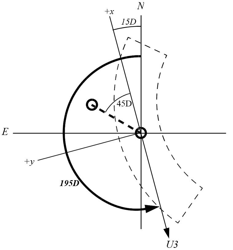
In this example we consider a close binary system in which the position angle of the line joining the stars is 60°. We wish to position the slit to exclude light from the companion star, so that the +Y axis (the long direction of the slit) is at -30°. The U3 axis (Table 6.2) lies at 45° from +Y, or at PA 15°. If a tolerance of 12° is allowed, we would then specify ORIENT 3° TO 27°. Because of the symmetry of the slit, it would also work if the orientation were flipped 180°, so the net specification is:
ORIENT 3° TO 27°
ORIENT 183° TO 207°
In this example we consider the same close binary system in which the position angle of the line joining the stars is 60°. The scans will be done parallel to the line joining the binary components, with a tolerance of 20°. TRANS mode scans move the instantaneous field of view at an angle of 45° relative to the FGS1 axes. The +X axis will have a PA of 60°, minus the 45° offset, or 15°. The U3 axis is 180° from +X (Table 6.2: Accuracies of Guiding Modes), thus we specify:
ORIENT 175° to 215°
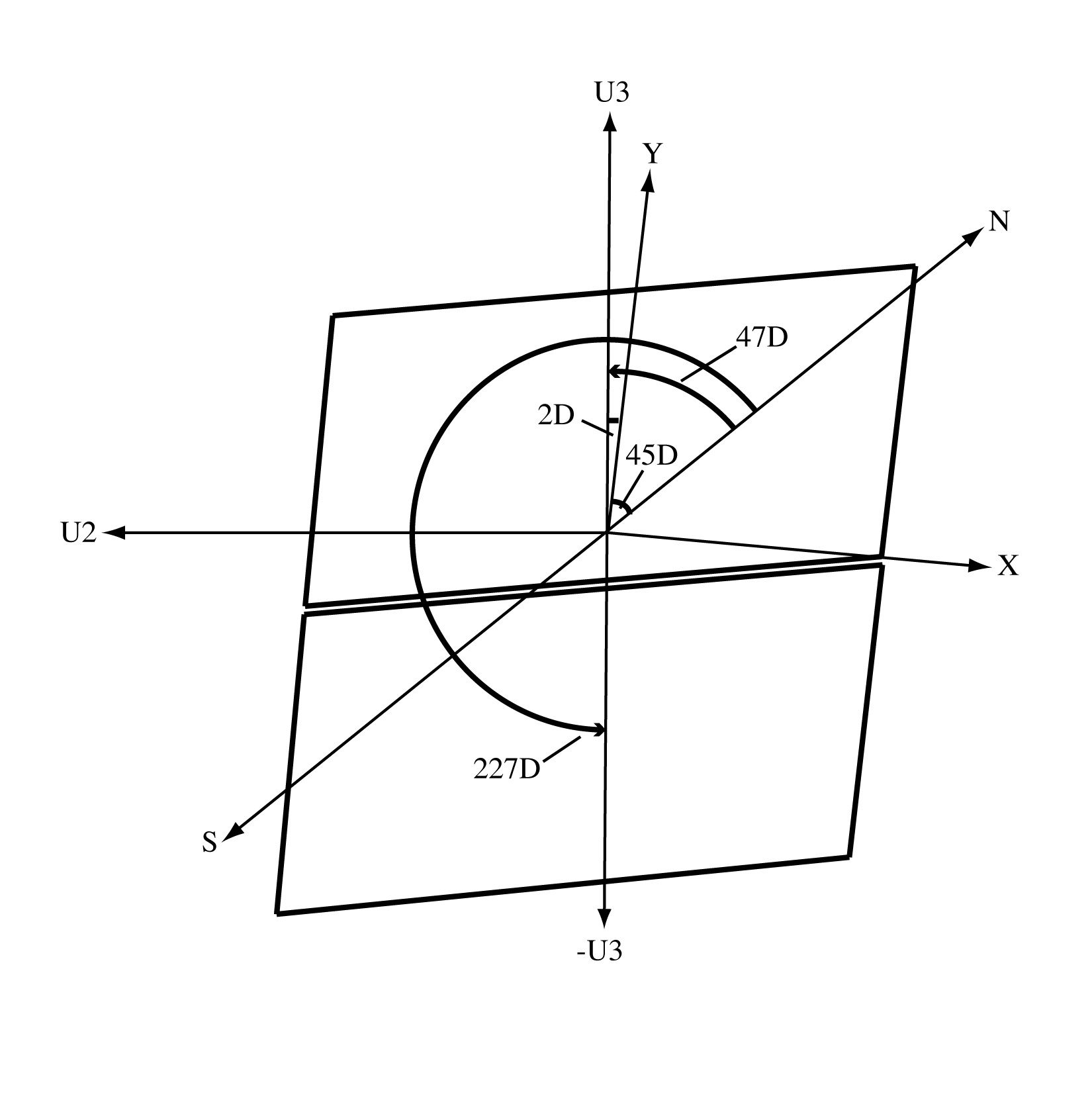
The target has a very bright neighboring star 10” away to the Northeast (PA = 45°). This star will saturate, leaving a bleeding trail along the entire y-axis of the detector. A user should therefore normally orient the telescope so that the bleeding trail does not run through the target; in other words, if keeping the target position at the same place on the chip, the bright star should be displaced from the target by means of an ORIENT which puts the offending star away from the target by +/- 10°. Adding an ORIENT constraint is the way to do this if wanting to keep the target at the nominal position with no x-axis displacement of the target, and is the primary purpose of this example. An alternate method if the ORIENT cannot be changed for some reason would be to displace the target position in the x-axis by some sufficient amount to avoid having the charge bleed down the same and adjacent y-axis columns onto the target. For larger extended targets, however, this method would require a much larger displacement of the target coordinates along the x-axis and may be impractical. Simply changing the ORIENT is the usual preferred method, or perhaps some combination of change in target position and ORIENT may help in some situations if absolutely necessary.
From Table 6.3: Approximate Separation and Orientations between the Science Instruments, we know that the U3 axis is 2° from the +y axis (measured north to east). Therefore, avoid the ORIENT angle that places the bright star on the y axis: 47° (45° + 2°, PA_star + angle from U3 to Y). Since blooming affects the entire detector y-axis, also avoid the angle 180° away, 227° (47° + 180°). For added caution, avoid +/- 10° about those angles. The ORIENTs to avoid are from 37° to 57° and from 217° to 237°. Therefore, keeping the same target position, it is safe to use ORIENT 57° TO 217° and ORIENT 237° TO 37°.
To control the placement of two instruments on an astronomical field in coordinated parallel exposures, one can make use of the angle between the U3 axis and the line connecting the centers of the two instruments. For example, to use aperture WFCENTER on ACS/WFC in parallel to aperture IR-FIX on WFC3/IR:
ORIENT=offset (WFC3 to ACS/WFC)+PAaxis (axis = vector from WFC3 to ACS/WFC)
For some of the visits in the Frontier Fields programs, the desired PAaxis was 280°. From Table 6.3: Approximate Separation and Orientations between the Science Instruments, the offset angle (WFC3 TO ACS/WFC) is 133°, so ORIENT = 133° + 280° = 413° = 53°.
Related Links
6.2.1 General Visit-level Special Requirements
6.2.3 Timing Visit-level Special Requirements
