2.6 FGS Aperture and Filter
2.6.1 FOV and Detector Coordinates
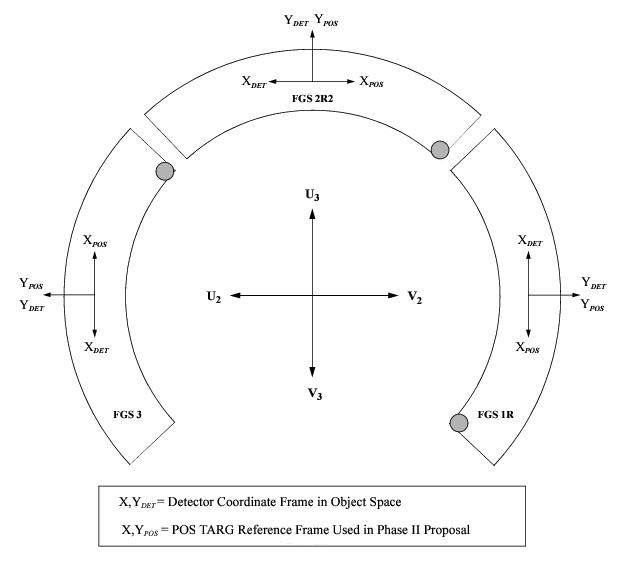
Figure 1.2 shows the HST focal plane positions of the FGSs as projected onto the sky. Figure 2.10 is similar, but includes the addition of two sets of axes: the FGS detector coordinate axes, and the POSTARG coordinate axes (used in the Phase II proposal instructions to express target offsets).
Each FGS FOV covers approximately 69 square arcmin, extending radially from 10 arcmin to 14 arcmin from the HST’s boresight and axially 83.3 degrees on the inner arc and 85 on its outer arc. The IFOV determined by the star selector assemblies and field stops is far smaller, covering only 5 × 5 arcsec. Its location within the pickle depends upon the Star Selector A and B rotation angles. To observe stars, the star selector assemblies must be rotated to bring the IFOV to the target. This procedure is called slewing the IFOV.
The (X,Y) location of the IFOV in the pickle is calculated from the Star Selector Encoder Angles using calibrated transformation coefficients. Each FGS has its own detector space coordinate system, the (X,Y)DET axes, as shown in Figure 2.10. FGS2 and FGS3 are nominally oriented at 90 and 180 degrees with respect to FGS1r, but small angular deviations are present (accounted for in flight software control and data reduction processing). The FGS detector reference frame is used throughout the pipeline processing. The POS TARG coordinate axes, (X,Y)POS, should be used to express offsets to target positions in the Phase II proposal (Special Requirements column). See 6.2.2 Target Orientation Visit-level Special Requirements.
The approximate U2,U3 coordinates for the aperture reference position (default placement of a target) for each FGS and the angle from the +U3 axis to the +YDET and +YPOS Axis are given in Table 2.3. The angles are measured from +U3 to +Y in the direction of +U2 (or counterclockwise in Figure 2.10). Note that the FGS internal detector coordinate reference frame and the POS TARG reference frame have opposite parities along their respective X-axes.
Table 2.3: Approximate Reference Positions of each FGS in the HST Focal Plane
Aperture | U2 | U3 | Angle (from +U3 axis) |
|---|---|---|---|
FGS1r | –723 | +10 | ~270 |
FGS2r2 | 0 | +729 | ~0 |
FGS3 | +726 | +6 | ~90 |
2.6.2 Filters and Spectral Coverage
Filter Bandpasses
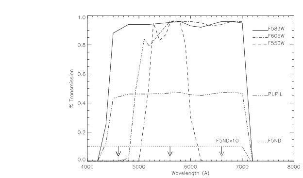
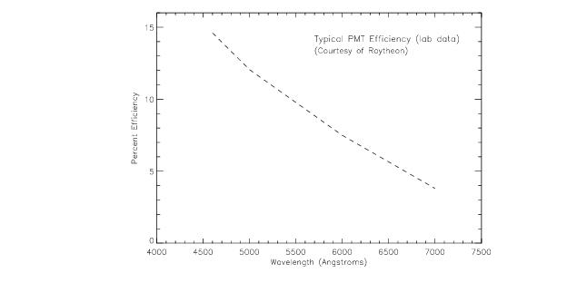
The filter wheel preceding the dielectric beam splitter in each FGS contains five 42mm diameter slots. Four of these slots house filters—F550W, F583W, F605W and F5ND—while the fifth slot houses the PUPIL stop. This stop helps restore the S-Curve morphology throughout the FOV of each FGS by blocking out the outer 1/3 perimeter of the spherically aberrated primary mirror. The filter selection for each FGS, their central wavelengths, and widths are listed in Table 2.4. The transmission curves (filters and PUPIL) are given in Figure 2.11. The PMT efficiency is given in Figure 2.12.
Filter | Central | Spectral Range | FWHM | FGS |
|---|---|---|---|---|
F583W | 5830 | 4600–7000 | 2340 | 1,1R,2,3 |
F605W | 6050 | 4800–7000 | 1900 | 1,1R,2 |
PUPIL | 5830 | 4600–7000 | 2340 | 1,1R,2,3 |
F550W | 5500 | 5100–5875 | 750 | 1,1R,2,3 |
F650W | 6500 | 6200–6900 | 750 | 3 |
F5ND | 5830 | 4600–7000 | 2340 | 1,1R,2,3 |


