4.2 Error Sources Associated with Pipeline Processing Steps
In this section, we discuss sources of error that are associated with major steps in the COS calibration pipeline (calcos). Note that these steps themselves were already described in Chapter 3 and will not be repeated here; this section will only describe specific issues related to the error budget of the resulting data which were not described before.
4.2.1 FUV Dark Count Rate
Dark counts arise from a combination of detector effects and external sources. Calcos will remove the effects of detector background (which includes dark, scattered light, etc.) in the BACKCORR module. This is done after the X1DCORR converts the detector image to a 1D extracted spectrum. Here, we discuss the instrumental contribution, since it can be the limiting factor in the error budget for very faint sources.
FUV-XDL Dark Count Rate
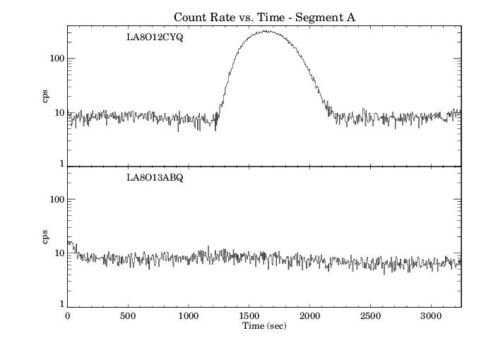
The FUV detector dark rates measured on the ground were very low, of order 0.4 counts cm–2 s–1. Typical dark rates on-orbit away from the South Atlantic Anomaly (SAA) are several times higher. The dark rates based on the 95th percentile of dark values obtained in 2021 are 2.01 × 10⁻⁶ counts pixel–1 s–1 for FUVA (corresponding to 1.40 counts cm–2 s–1) and 1.70 × 10⁻⁶ counts pixel–1 s–1 for FUVB (1.18 counts cm–2 s–1). This is equivalent to 1.21 × 10⁻⁴ counts s–1 per resolution element (FUVA) and 1.02 × 10⁻⁴ counts s–1 per resolution element (FUVB). These rates have remained relatively stable since SM4, although there are sometimes large variations seen on short timescales. The behavior of the dark rates versus time can be seen on these monitoring pages for FUVA and FUVB. For the most up to date numbers, please refer to the current version of the COS Instrument Handbook, Section 7.4.1.
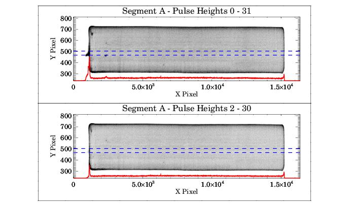
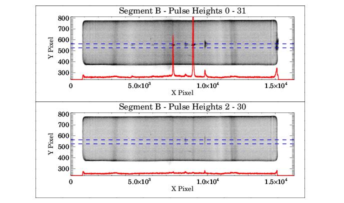
The spatial distribution of background counts on Segment A is fairly uniform, independent of pulse height thresholding or proximity to the SAA (Figure 4.2). For segment B, however, there are a number of features in the region where the spectra fall when all pulse heights are included. Most of these features disappear when the appropriate pulse height thresholding (used by default in the calcos pipeline for TIME-TAG data) is applied, as shown in Figure 4.3.
There is an additional complication to the FUV dark correction. As the FUV detectors have been exposed to more light, the portion of the detectors where the spectrum falls has become less sensitive due to gain sag. This sensitivity loss even affects the dark count rate. As a result, the background, which is estimated from rarely illuminated regions on either side of the science spectrum, tends to overestimate the dark rate at the location of the spectrum and, therefore, to overcorrect the spectrum. This effect is small, and only affects very faint objects. Nevertheless, one should be aware of it. We note that the darks are time and LP dependent.
4.2.2 Flat Fields
NUV-MAMA Flat Fields
The STIS MAMA flat fields are dominated by a fixed pattern that is a combination of several effects including "beating" between the micro-channel plates and the anode pixel array and variations in the charge cloud structure at the anode. Similar effects are present in the COS MAMA. Intrinsic pixel-to-pixel variations measured on the ground for the COS NUV-MAMA were 5.2% rms. Analysis of the COS NUV flat-field taken during servicing mission orbital verification (SMOVs) by Ake et al. (COS ISR 2010-03) found that it aligned to within one pixel of the flat field created during ground testing. Consequently, all SMOV and ground data were combined to produce a single flat field reference file for pipeline processing.
The reference file does not correct vignetting, which affects X pixels with values between 0 and 200. The vignetting can eliminate as much as 20% of the flux from X = 0 to 100, and then the fraction of flux vignetted slowly decreases to 0 between X = 100 and 200. Since the amount of vignetting depends on the angle of illumination, and because the OSM positions are not perfectly repeatable, simple corrections are inadequate. Due to the low usage of the NUV channel, a more complex solution has not been pursued.
Studies of the on-orbit S/N achievable indicate that the Poisson limit can be reached for S/N < 70 and that an S/N > 150 can be achieved by combining high S/N exposures obtained at different FP-POS settings over most of the detector. However, the variable vignetting can introduce large, spatially coherent errors over the first 200 pixels of each stripe of the NUV spectra.
FUV-XDL Flat Fields
The FUV XDL detector has considerable fixed-pattern noise. These include dead spots, variable hot spots, a honeycomb pattern due to the manufacturing process used to produce the MCP, and shadows from the repeller grid wires. A full, two-dimensional flat field obtained during internal ground tests did not produce the signal-to-noise needed for a useful flat, and it has been deemed too costly in terms of exposure time and impact on detector lifetime to fully characterize the COS flat field using on-orbit observations.
Nevertheless, some progress has been made. The FUV flat field corrects for the grid wire shadows, which are the largest single source of fixed-pattern noise, some features near the edges of segment B (the so-called "imposter" grid wires), and low-order variations in the detector response.
Note that even with the correction of the grid wire shadows, other large amplitude (up to 10%) fixed-pattern features remain in the spectra. At present, the best approach to mitigate these is to combine observations obtained at different FP-POS settings. A complete description of the G130M and G160M grid wire flats, and estimates for the achievable S/N for these gratings from normally processed data, are given in COS ISR 2011-03.
4.2.3 Gain Sag
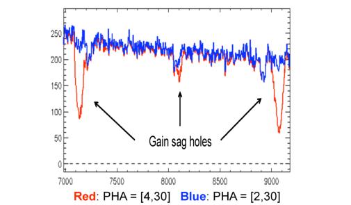
As described in Chapter 1, the pulse height for photons incident on the COS XDL FUV detector varies with position on the detector and changes with time. The typical peak pulse height (modal gain) decreases as the total exposure at that location increases; this effect is known as gain sag (see COS ISR 2011-05). The regions of the detector which have collected the most photons are the parts of Segment B that are exposed to the bright Lyα airglow line while using the G130M grating. In particular, regions near pixels 7150 and 9100 are most strongly affected. When the sag is large, PHA values can fall below the calcos thresholds and are discarded by the pipeline. Figure 4.4 shows the effect of changing the lower PHA cutoff from 4 to 2 on these features. With a PHA cutoff of 4, the total number of counts in the most heavily sagged regions is depressed by nearly 50%. In contrast, with a PHA cutoff of 2, the gain sag regions are depressed by approximately 10%.
The MCP gain can be increased by raising the high voltage on the affected detector segment. This is done at regular time intervals in order to keep the loss of flux due to gain sag to within data quality requirements. Nominal values of detector high voltage used on orbit are listed in Appendix B.
The gain in the spectral region can also be increased by moving the spectra to a part of the detector which has seen fewer counts. These moves of the Lifetime Position (LP) have been made several times since SMOV. In addition, the COS2025 policy limits the cenwave and FP-POS selections for G130M segment B observations. See Appendix A for details.
In order to address the effects of gain sag, the COS FUV detector high voltage has been raised numerous times since the instrument was installed, and the spectra have been shifted to new lifetime positions. For details on these adjustments consult Appendix A and Appendix B.
4.2.4 FUV XDL Thermal Drifts
The XDL centroiding electronics are sensitive to thermal effects. The TEMPCORR module of calcos measures the location of the stim pulses in order to determine the shift and stretch of the detector format and correct for any changes; TEMPCORR applies a linear correction based on the position of these stim pulses. The accuracy of this correction will influence the ability to properly register the flat field corrections and may influence the final error budget.


