5.2 Evaluating Target Acquisitions and Guiding
COS target acquisitions and the options available to the observer are fully described in the COS Instrument Handbook. If you are examining COS observations that were specified by another observer, please refer to the instrument handbook to understand the options and parameters that may have been used.
Virtually all COS observations start with one or more acquisition exposures. The purpose of the acquisition is to ensure that the object observed is well centered in the COS aperture being used so as to avoid throughput losses and to produce a reliable wavelength zero point. Examining the acquisition data should allow you to detect significant errors in the centering of the target. Note that target acquisition data are always uncalibrated.
5.2.1 Types of Target Acquisitions
There are two types of COS acquisitions: imaging and dispersed-light. In an imaging acquisition, the COS NUV channel is used to obtain an image of the target in the COS aperture. This image is then analyzed by the COS flight software, the object's centroid is calculated, and the object is centered in the aperture. A dispersed-light acquisition directly analyzes the spectrum of the object being acquired and determines how to center the object so as to maximize throughput. Both types of COS acquisitions are intended to work on point sources or point-like sources.
ACQ/SEARCH
A sequence of observations may begin with an ACQ/SEARCH, either in imaging mode or in dispersed-light mode (see the COS Instrument Handbook for a full description). The optical element selected will appear in the ACQ file header: either a grating (and central wavelength) for dispersed light, or a mirror (MIRRORA or MIRRORB) for imaging. In either case, the telescope is commanded to move in a square spiral pattern, and at each dwell point an exposure is taken. The STEP-SIZE parameter sets the spacing between dwell points; the default is 1.767 arcsec, the optimum size to ensure that no area of sky is missed. The SCAN-SIZE parameter sets the number of dwells on each side of the square; the choices are 2, 3, 4, or 5. If an even number of points is used (SCAN-SIZE = 2 or 4), the first point is offset by half the STEP-SIZE in both directions so that the overall pattern remains centered on the initial pointing.
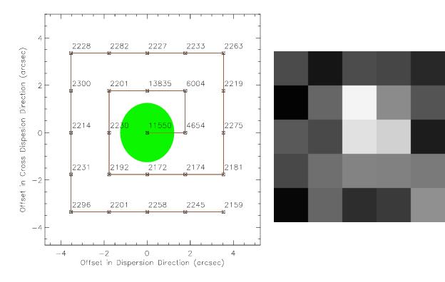
The data from an ACQ/SEARCH exposure consists of a header and a binary table data extension which contains the accumulated counts at each dwell point, see Table 2.11. This array of counts was processed by the flight software to calculate the centroid and the telescope was then commanded to move to that centroid. A quick verification that an ACQ/SEARCH exposure was successful would be to find the values of the XDISP_OFFSET and DISP_OFFSET columns of the ACQ/SEARCH data table corresponding to the maximum counts value at a single dwell point. Then, compare the XDISP_OFFSET and DISP_OFFSET values to the ACQSLEWX and ACQSLEWY header keyword values (see Table 2.7). Similarly, the data can be easily plotted for quick visual verification (see Figure 5.1).
ACQ/SEARCH spiral pattern showing the offsets in the dispersion and cross dispersion directions from the initial pointing for each dwell point with the counts at each dwell point overplotted. The green circle in the center represents the science aperture and the initial pointing. Right: Linearly scaled image of the counts at each dwell point for the same 5 × 5 ACQ/SEARCH exposure (where white shows the most counts).Undispersed Light (Imaging) Acquisitions (ACQ/IMAGE)
When the ACQ/IMAGE command is used, two ACCUM exposures in imaging mode are taken for the specified exposure time, using the NUV channel of COS. The first exposure is taken after the initial pointing by HST and is used by the flight software to determine the centroid of the object and the amount of pointing change needed to center the object in the aperture (PSA or BOA). The center of the aperture is computed from the image of the Wavelength Calibration Aperture (WCA) and the known WCA-PSA offset specified on the flight software. The second image is taken after the object is centered to confirm that proper centering occurred. Each of the two images uses a sub-array of size 816 × 345 (in user coordinates) on the COS NUV MAMA. The commanded motions of the telescope in x and y are provided in the ACQ/IMAGE header. The _rawacq file contains the initial target image as a 1024 × 1024 array, followed by the confirmation image, another array of the same size.
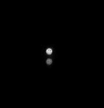
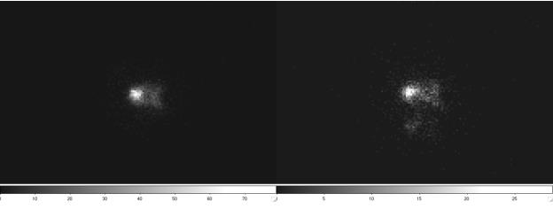
The appearance of the image of a point source recorded by COS in ACQ/IMAGE mode will depend on the aperture used (PSA or BOA) and the mirror (MIRRORA or MIRRORB). The best optical quality is achieved with the PSA used with MIRRORA, in which case a diffraction-limited image is created with a tight core. If MIRRORB was used instead to attenuate the source, two images of the source are produced (Figure 5.2). If the BOA was used, a neutral-density filter attenuates the source, but that filter has a slight wedge shape that degrades optical quality. Figure 5.3 shows images of point sources obtained with the BOA using MIRRORA and MIRRORB. Profiles of images taken with various combinations of (PSA, BOA) and (MIRRORA, MIRRORB) are shown in the COS Instrument Handbook.
The data produced by ACQ/IMAGE can be used to confirm proper acquisition of an object, by direct comparison of the two images.
PSA and MIRRORB.
BOA and MIRRORA (left), and the BOA and MIRRORB (right).
BOA and MIRRORA (left), and the BOA and MIRRORB (right).Dispersed-Light Acquisitions (ACQ/PEAKD and ACQ/PEAKXD)
As noted above, an ACQ/SEARCH exposure can be performed in dispersed light. In that case, the file header will show a grating and central wavelength for the optical element chosen. As for an ACQ/IMAGE, any acquisition performed in dispersed light can use either aperture: the PSA or BOA. In addition to ACQ/SEARCH, two other commands are available to improve the centering of an object in dispersed light: ACQ/PEAKXD and ACQ/PEAKD.
An ACQ/PEAKXD should always precede an ACQ/PEAKD if both are performed. An ACQ/PEAKXD centers the spectrum in the cross-dispersion direction by obtaining a short exposure, calculating the centroid, and moving the telescope by that amount. Users will only receive files with headers containing the commanded movement of the telescope for ACQ/PEAKXD exposures. A quick verification that an ACQ/PEAKXD exposure was successful would be to compare the ACQSLEWY and (ACQPREFY –ACQMEASY) header keyword values (see Table 2.7).
An ACQ/PEAKD centers the spectrum along the dispersion direction by executing a series of short exposures with the telescope moving the source in a line for a specified number of points (SCAN-SIZE), spaced by STEP-SIZE arcsec (effectively a 1-D ACQ/SEARCH). A centroid is calculated, and the same options available for an ACQ/SEARCH are also available for an ACQ/PEAKD. Following the centroid calculation, the telescope is moved to center the source, and the counts at each dwell point are recorded in a table, see Table 2.11. Users may compare the offsets associated with the dwell point containing the maximum counts to the telescope slews recorded in the header. A quick verification that an ACQ/PEAKD exposure was successful would be to find the value of the DISP_OFFSET column of the ACQ/PEAKD data table corresponding to the maximum counts value at a single dwell point. Then, compare the DISP_OFFSET value to the ACQSLEWX header keyword values (see Table 2.7). The data can also be easily plotted for a quick visual verification, similar to what is shown in Figure 5.1 for the ACQ/SEARCH example.
5.2.2 Guiding Errors for Single-Guide-Star Mode
Tracking on two guide stars should provide pointing accuracy sufficient to keep targets centered in the COS aperture for several orbits. However, in some cases, observations are made using only a single guide star instead of the usual two. Either the General Observer has consented to this in consultation with the Program Coordinator when two suitable guide stars could not be found, or one Fine Guidance Sensor failed to acquire its guide star during the guide star acquisition/reacquisition. In this situation, the roll of the telescope is under GYRO control, which may allow a slow drift of the target on a circular arc centered on the single guide star. The drift rate along this arc (rate of rotation) depends on the characteristics of the pointing for any particular observation, but typical values are expected to be in the range of 1.0 to 1.5 milliarcsec/sec (possibly, but very rarely, as large as 5 milliarcsec/sec).
To calculate the approximate magnitude of the drift of the target on the detector, you will need to find the distance of the target from the acquired guide star. The primary header of the observation log file jif identifies the acquired guide star (GSD_ID) and gives its right ascension (GSD_RA) and declination (GSD_DEC) in degrees. For example, for a target 10 arcmin from the guide star, a drift of the target around the guide star of 1 milliarcsec/sec during a 1,000 second exposure would cause the target to move 0.0029 arcsec on the detector. The direction of the motion on the detector can be deduced from header keywords in the science data describing the position angle of the detector (e.g., PA_APER) in combination with the direction perpendicular to the radiant. In many cases, the drift will be a small fraction of a pixel, although in some cases an image exposure may appear smeared.


