3.1 The Optical Design of COS
In most spectrographs the light from the telescope is focused onto a slit, which is then re-imaged onto the detector. In such a design the slit width and the way that the slit is illuminated determine the resolving power and Line Spread Function (LSF). COS is different. It is essentially a slitless spectrograph with an extremely small field of view. In this section we follow the light from the HST Optical Telescope Assembly (OTA) as it progresses through COS to each optical element and mechanism. The optical path and mechanism locations are shown in Figure 3.1.
3.1.1 External Shutter
The external shutter is located at the front of the COS enclosure. When closed the shutter blocks all external light from entering the COS instrument and prevents light from the COS internal lamps from exiting the instrument. The opening and closing of the external shutter does not define the duration of an exposure, as the shutter may be opened before an exposure begins to allow for target acquisition and bright-object checking.
Figure 3.1: The COS Optical Path and the Locations of the Mechanisms.
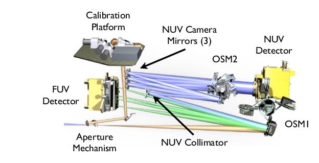
The optical path is drawn to scale while the optical elements are to a different scale.
3.1.2 The Apertures and Aperture Mechanism
After passing through the external shutter, the light from the OTA first encounters one of the COS entrance apertures (Table 3.1), which are mounted on the Aperture Mechanism (ApM). Selecting an aperture can involve movement of the Aperture Mechanism.
Primary Science Aperture
The Primary Science Aperture (PSA) is a circular field stop 2.5 arcsec (700 μm) in diameter. It is located, not at the HST focal surface, but near the point of the circle of least confusion. The aperture transmits ≥ 95% of the light from a well-centered, aberrated point-source image delivered by the HST optics. The PSA is used for almost all COS science observations. It is in place, ready to use, at the start of a new visit. For LP1-LP5 and LP10, note that, when the PSA is in place, the Wavelength Calibration Aperture (WCA; see below) is also in place and available to acquire simultaneous wavelength-calibration spectra. External light entering the PSA and internal light entering the WCA are dispersed by the same grating. Thus, for a given grating and central-wavelength setting, no additional motion of the Aperture Mechanism is required to obtain a wavelength-calibration exposure. However, at LPs high on the detector (LP6 and LP7), this is not true. At LPs above 5 in relation to LP1, a light leak prevents concurrent wavecal flashes requiring SPLIT wavecals (See Section 5.7.6).
Table 3.1: COS Entrance Apertures.
Aperture | Full Name | Purpose | Size (mm) |
|---|---|---|---|
PSA | Primary Science Aperture | science aperture | 0.700 diameter |
BOA | Bright Object Aperture | science aperture with ND2 filter | 0.700 diameter |
WCA | Wavelength Calibration Aperture | wavecals with Pt-Ne lamp | 0.020 × 0.100 |
FCA | Flat-Field Calibration Aperture | Flat field with deuterium lamp | 0.750 × 1.750 |
Wavelength Calibration Aperture
The Wavelength Calibration Aperture (WCA) is offset from the PSA by 2.5 mm in the cross-dispersion direction. The WCA is illuminated by one of two Pt-Ne wavelength-calibration (wavecal) lamps. It does not receive light from external sources. The wavecal spectrum is used by the COS pipeline to assign wavelengths to the science spectra obtained through either the PSA or BOA. During target acquisitions light from the Pt-Ne lamps provides a reference from which the location of the target aperture is determined.
Bright Object Aperture
Like the PSA, the Bright Object Aperture (BOA) is 2.5 arcsec (700 μm) in diameter, but it incorporates a neutral-density (ND2) filter. The transmission of the ND2 filter varies with wavelength (Figure 3.2), but is roughly 0.6%. The BOA is offset from the PSA by 3.7 mm (about 13 arcsec) in the cross-dispersion direction opposite the WCA. For scientific observations the aperture block is shifted, via movement of the Aperture Mechanism, to place the BOA in the position normally occupied by the PSA. Thus, spectra obtained through either the PSA or BOA use the same optical path and detector region (for a given channel), and so may employ the same fixed pattern calibrations. Moving the BOA into place for scientific use shifts the WCA as well, precluding simultaneous use of the WCA for a wavecal exposure. Before or after an observation through the BOA the Aperture Mechanism must be moved to properly position the WCA, so that a wavecal exposure may be obtained. Currently, the BOA has not been calibrated to the same accuracy as other modes and is an available-but-unsupported option.
Flat-Field Calibration Aperture
The Flat-Field Calibration Aperture (FCA) is used to obtain flat-field exposures using one of the two deuterium hollow-cathode flat-field calibration lamps. The FCA is used only for calibration and is not available to general observers.
3.1.3 Gratings and Mirrors: The Optics Select Mechanisms
After passing through one of the COS apertures light next encounters the Optics Select Mechanism 1 (OSM1), a rotating mechanism that can bring one of four optical elements into the beam. One of these, NUV Collimating Mirror 1 (NCM1), is a flat mirror that directs the beam to the NUV channel. The other three elements are the G130M, G160M, and G140L gratings for the FUV channel. As a consequence of this design the FUV and NUV channels cannot be used simultaneously.
Figure 3.2: Transmission of the COS BOA as a Function of Wavelength.
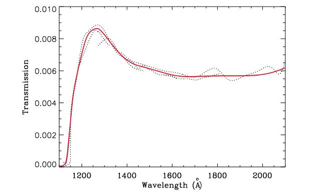
Ratio of BOA sensitivity curves derived from observations of GD71 to PSA sensitivity curves derived from observations of LDS749b (dashed curves). The thick red curve is a spline fit to the dashed curves, giving a uniform BOA transmission curve as a function of wavelength.
Figure 3.3: The COS FUV Optical Path.
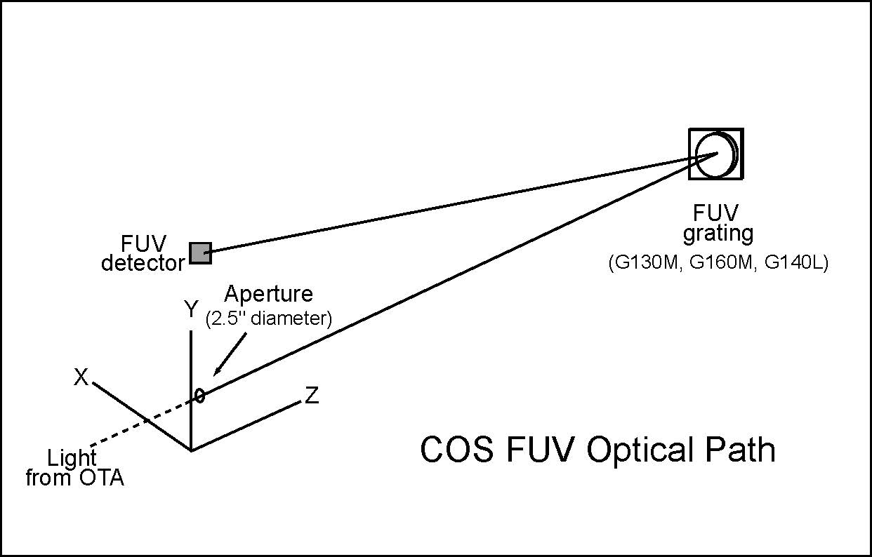
The optical path is drawn to scale.
FUV Channel Optical Design
The COS FUV optical path is illustrated schematically in Figure 3.3. To maximize throughput a single FUV grating is used to disperse the light, remove the spherical aberration introduced by the HST primary mirror, and focus the beam onto the detector. Because the FUV gratings introduce astigmatism in the direction perpendicular to dispersion, the height of the spectrum varies with wavelength (Section 5.1.9). Given the location of OSM1 in the HST optical path it is possible for the FUV gratings to disperse, focus, and correct the beam optimally only for a point source that is centered in the aperture. Performance is degraded when the source is moved away from the aperture center. Fortunately, this degradation is low for displacements up to about 0.4 arcsec (Section 8.8).
The COS FUV channel provides spectra from 900 to 2150 Å at low and moderate spectral resolution (Section 5.1). The FUV detector is described fully in Chapter 4, but it is important to note that it consists of two independent detector segments with a small physical gap between them. Light falling into the gap is not recorded. Though the gap prevents a continuous spectrum from being obtained at a single central-wavelength setting, the missing wavelengths can be recovered by obtaining additional exposures at other central-wavelength settings (corresponding to small rotations of the OSM1 mechanism; see Section 5.5).
Moving Spectra to Different Lifetime Positions on the FUV Detector
To optimize the longevity and performance of the COS FUV detector, spectra can be moved to different Lifetime Positions (LPs) on the detector (Section 5.12). Unlike mechanical adjustments within the optical path, this movement is achieved by tilting the entire telescope slightly in the cross-dispersion direction and adjusting the aperture position. This tilt alters the angle at which light from the object under observation enters the system, resulting in a shift in the spectrum’s position on the detector. The FUV grating, which functions similarly to a mirror along the cross-dispersion axis, reflects the incoming light, and this small adjustment in the telescope’s angle moves the light to a new postition on the detector. This change in angle also degrades from the original resolving power of the spectrograph at LP1.
POS TARG Adjustments
When adjusting the POS TARG position in APT, the telescope’s tilt is modified by a corresponding amount in arcseconds, causing the spectrum to shift in the dispersion (X POS TARG) or cross-dispersion direction by a specific number of pixels. For instance, a Y POS TARG of 'A' results in a shift of 'A' arcseconds.
Detector Plate Scale
Because the aperture is only 2.5 arcsec in diameter, significant tilts may require adjustments to ensure that the light from the target still reaches the grating. It is important to note that while this movement is often described in arcseconds, this refers to the angle of the telescope’s tilt rather than the exact position on the detector, which is measured in pixels. The relationship between these two measurements is not strictly linear. As such, users should note that exact values of plate scale are dependent on employed Lifetime Position.
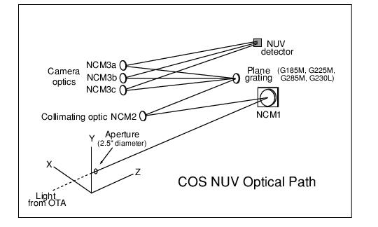
Figure 3.4: The COS NUV Optical Path for Spectroscopic Observations.
OSM2 and the NUV Channel
The COS NUV channel, illustrated schematically in Figure 3.4, provides coverage from about 1650 to 3200 Å at low and moderate spectral resolution. If the NUV channel is to be used OSM1 is turned to place mirror NCM1 in the beam. NCM1 corrects the beam for the spherical aberration of HST, magnifies it by a factor of four, and directs it to the NUV Collimating Mirror 2 (NCM2). The NCM2 collimates the light and directs it to Optics Select Mechanism 2 (OSM2). OSM2 holds five optical elements: the four NUV diffraction gratings (G185M, G225M, G285M, and G230L), and a mirror for target acquisitions or imaging.
To accommodate the NUV detector format, dispersed light from the NUV gratings is imaged onto the detector by three parallel mirrors (NCM3a, 3b, 3c). For the medium-dispersion gratings the spectra appear as three non-contiguous 35−40 Å stripes on the MAMA detector, providing 105−120 Å wavelength coverage per exposure. The low-dispersion grating provides ~400 Å per stripe. The layout of the stripes is shown in Figure 4.9. The gratings can be shifted via slight rotations of OSM2 to cover the entire NUV wavelength band. The NCM3 mirrors are spaced such that several correctly-chosen exposures will produce a complete spectrum, from the low end of the short-wavelength stripe to the high end of the long-wavelength stripe.
Imaging with the NUV Mirror
For imaging observations OSM2 is turned to place a mirror (TA1) in the light path instead of a grating (Figure 3.5). When used in direct specular reflection this mirror is designated as MIRRORA. For bright targets, the flux can be attenuated by adjusting OSM2 so that the order-sorting filter in front of the mirror reflects the light onto the detector. This configuration is referred to as MIRRORB. COS imaging is described in Chapter 6.
Figure 3.5: COS NUV Optical Path for Imaging Observations.
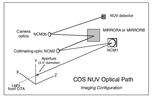
-
COS Instrument Handbook
- Acknowledgments
- Chapter 1: An Introduction to COS
- Chapter 2: Proposal and Program Considerations
- Chapter 3: Description and Performance of the COS Optics
- Chapter 4: Description and Performance of the COS Detectors
-
Chapter 5: Spectroscopy with COS
- 5.1 The Capabilities of COS
- • 5.2 TIME-TAG vs. ACCUM Mode
- • 5.3 Valid Exposure Times
- • 5.4 Estimating the BUFFER-TIME in TIME-TAG Mode
- • 5.5 Spanning the Gap with Multiple CENWAVE Settings
- • 5.6 FUV Single-Segment Observations
- • 5.7 Internal Wavelength Calibration Exposures
- • 5.8 Fixed-Pattern Noise
- • 5.9 COS Spectroscopy of Extended Sources
- • 5.10 Wavelength Settings and Ranges
- • 5.11 Spectroscopy with Available-but-Unsupported Settings
- • 5.12 FUV Detector Lifetime Positions
- • 5.13 Spectroscopic Use of the Bright Object Aperture
- Chapter 6: Imaging with COS
- Chapter 7: Exposure-Time Calculator - ETC
-
Chapter 8: Target Acquisitions
- • 8.1 Introduction
- • 8.2 Target Acquisition Overview
- • 8.3 ACQ SEARCH Acquisition Mode
- • 8.4 ACQ IMAGE Acquisition Mode
- • 8.5 ACQ PEAKXD Acquisition Mode
- • 8.6 ACQ PEAKD Acquisition Mode
- • 8.7 Exposure Times
- • 8.8 Centering Accuracy and Data Quality
- • 8.9 Recommended Parameters for all COS TA Modes
- • 8.10 Special Cases
- Chapter 9: Scheduling Observations
-
Chapter 10: Bright-Object Protection
- • 10.1 Introduction
- • 10.2 Screening Limits
- • 10.3 Source V Magnitude Limits
- • 10.4 Tools for Bright-Object Screening
- • 10.5 Policies and Procedures
- • 10.6 On-Orbit Protection Procedures
- • 10.7 Bright Object Protection for Solar System Observations
- • 10.8 SNAP, TOO, and Unpredictable Sources Observations with COS
- • 10.9 Bright Object Protection for M Dwarfs
- Chapter 11: Data Products and Data Reduction
-
Chapter 12: The COS Calibration Program
- • 12.1 Introduction
- • 12.2 Ground Testing and Calibration
- • 12.3 SMOV4 Testing and Calibration
- • 12.4 COS Monitoring Programs
- • 12.5 Cycle 17 Calibration Program
- • 12.6 Cycle 18 Calibration Program
- • 12.7 Cycle 19 Calibration Program
- • 12.8 Cycle 20 Calibration Program
- • 12.9 Cycle 21 Calibration Program
- • 12.10 Cycle 22 Calibration Program
- • 12.11 Cycle 23 Calibration Program
- • 12.12 Cycle 24 Calibration Program
- • 12.13 Cycle 25 Calibration Program
- • 12.14 Cycle 26 Calibration Program
- • 12.15 Cycle 27 Calibration Program
- • 12.16 Cycle 28 Calibration Program
- • 12.17 Cycle 29 Calibration Program
- • 12.18 Cycle 30 Calibration Program
- • 12.19 Cycle 31 Calibration Program
- • 12.20 Cycle 32 Calibration Program
- • 12.21 Cycle 33 Calibration Program
- Chapter 13: COS Reference Material
- • Glossary