4.2 The NUV MAMA Detector
4.2.1 MAMA Properties
The COS NUV detector is a Multi-Anode Micro-channel Array (MAMA) identical to that used for the NUV in STIS. (In fact, it is the STIS NUV flight spare.) The COS MAMA has a semi-transparent cesium telluride photocathode on a magnesium fluoride window and is sensitive to photons with wavelengths from 1150 to 3200 Å. The NUV optics focus light through the MgF2 window onto the Cs2Te photocathode. A photoelectron generated by the photocathode then falls onto a curved-channel micro-channel plate (MCP), which generates a cloud of electrons. The active area of the anode array is 25.6 mm square and is divided into 1,024 × 1,024 pixels on 25 μm centers. The spatial resolution at 2500 Å is 35 μm FWHM. Detector parameters are listed in Table 1.2.
4.2.2 MAMA Spectrum Response
The inherent spectral response of the COS NUV MAMA is essentially identical to that of the STIS NUV MAMA. However, the overall optical train of COS differs from that of STIS, so the throughputs are different (Figure 5.2). The maximum count rates for the NUV detector are listed in Table 10.1.
4.2.3 MAMA Dark Rate
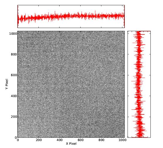
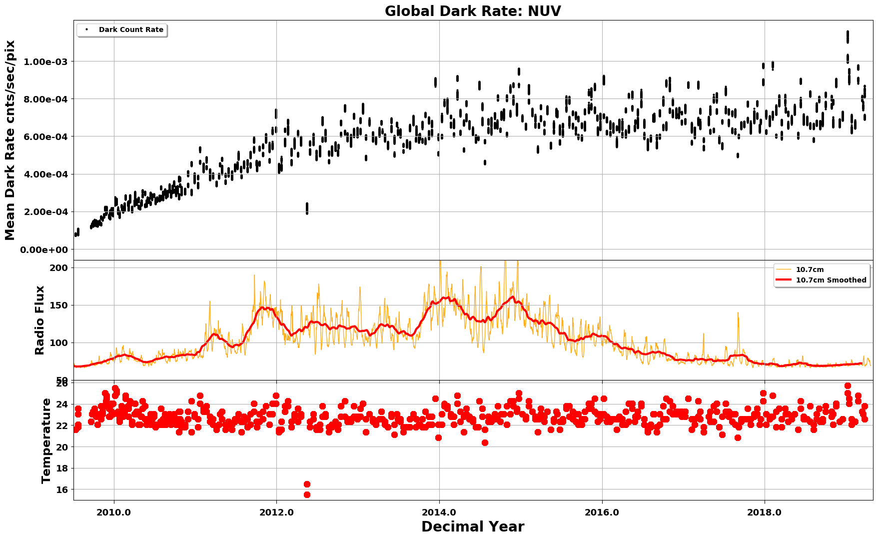
A sum of dark exposures taken away from the SAA shows a relatively featureless background, with slight enhancements at two of the corners (Figure 4.7). Although the early dark rate was lower than had been measured on the ground, the rate has steadily increased since launch, as shown in Figure 4.8. For version 31.2 of the COS ETC, the dark rate adopted for NUV is 1.25 × 10⁻³ counts s-1 pixel-1, encompassing 95% of observations through 2023. A webpage which monitors dark rates can be found at https://www.stsci.edu/hst/instrumentation/cos/performance/monitoring.
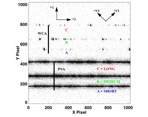
TIME-TAG mode with FLASH=YES. The stellar spectrum (labeled PSA) is on the bottom, and the wavelength-calibration spectrum (labeled WCA) on the top; each has three stripes. From bottom to top, these stripes are designated A, B, and C, as illustrated. Wavelength increases to the right and toward the top of the detector. The HST +V2 and +V3 axes are also shown. The SHORT, MEDIUM, and LONG designations are used in Phase II with the ACQ/PEAKXD command and the STRIPE optional parameter.4.2.4 MAMA Read-Out Format
The NUV channel creates six spectral stripes on the MAMA detector, three for the science data and three for the wavelength-calibration data. Stripes are separated by 94 to 143 pixels (2.1 to 3.3 arcsec), center to center, in the cross-dispersion direction. The NUV detector is read out as a 1,024 × 1,024 array, but in all other respects the data are handled in the same way as for the FUV detector. No pulse-height information is provided for MAMA data. An NUV spectrum obtained in TAGFLASH mode is shown in Figure 4.9.
4.2.5 MAMA Dead Time
The dead time for the COS NUV MAMA is 280 ns, the same as for the STIS NUV MAMA. The 1% level of non-linearity is reached for C = 36,000 count/s. Corrections for dead-time effects are made in the CalCOS pipeline, but they are not included in the ETC, which will over-predict count rates for bright targets.
4.2.6 Non-Gaussian Wings in the MAMA PSF
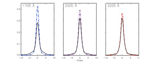
While most NUV observations should be minimally affected by the mid-frequency wavefront errors (MFWFEs) discussed in Section 3.3, they will reflect the point-spread function of the COS MAMA detector, which exhibits faint, extended wings that are unrelated to the telescope optics. While the telescope-induced wings weaken as wavelength increases, the detector wings become stronger with increasing wavelength. Figure 4.10 shows model NUV detector LSFs with and without the MFWFEs at various wavelengths. Beyond 2500 Å, the detector wings dominate.
-
COS Instrument Handbook
- Acknowledgments
- Chapter 1: An Introduction to COS
- Chapter 2: Proposal and Program Considerations
- Chapter 3: Description and Performance of the COS Optics
- Chapter 4: Description and Performance of the COS Detectors
-
Chapter 5: Spectroscopy with COS
- 5.1 The Capabilities of COS
- • 5.2 TIME-TAG vs. ACCUM Mode
- • 5.3 Valid Exposure Times
- • 5.4 Estimating the BUFFER-TIME in TIME-TAG Mode
- • 5.5 Spanning the Gap with Multiple CENWAVE Settings
- • 5.6 FUV Single-Segment Observations
- • 5.7 Internal Wavelength Calibration Exposures
- • 5.8 Fixed-Pattern Noise
- • 5.9 COS Spectroscopy of Extended Sources
- • 5.10 Wavelength Settings and Ranges
- • 5.11 Spectroscopy with Available-but-Unsupported Settings
- • 5.12 FUV Detector Lifetime Positions
- • 5.13 Spectroscopic Use of the Bright Object Aperture
- Chapter 6: Imaging with COS
- Chapter 7: Exposure-Time Calculator - ETC
-
Chapter 8: Target Acquisitions
- • 8.1 Introduction
- • 8.2 Target Acquisition Overview
- • 8.3 ACQ SEARCH Acquisition Mode
- • 8.4 ACQ IMAGE Acquisition Mode
- • 8.5 ACQ PEAKXD Acquisition Mode
- • 8.6 ACQ PEAKD Acquisition Mode
- • 8.7 Exposure Times
- • 8.8 Centering Accuracy and Data Quality
- • 8.9 Recommended Parameters for all COS TA Modes
- • 8.10 Special Cases
- Chapter 9: Scheduling Observations
-
Chapter 10: Bright-Object Protection
- • 10.1 Introduction
- • 10.2 Screening Limits
- • 10.3 Source V Magnitude Limits
- • 10.4 Tools for Bright-Object Screening
- • 10.5 Policies and Procedures
- • 10.6 On-Orbit Protection Procedures
- • 10.7 Bright Object Protection for Solar System Observations
- • 10.8 SNAP, TOO, and Unpredictable Sources Observations with COS
- • 10.9 Bright Object Protection for M Dwarfs
- Chapter 11: Data Products and Data Reduction
-
Chapter 12: The COS Calibration Program
- • 12.1 Introduction
- • 12.2 Ground Testing and Calibration
- • 12.3 SMOV4 Testing and Calibration
- • 12.4 COS Monitoring Programs
- • 12.5 Cycle 17 Calibration Program
- • 12.6 Cycle 18 Calibration Program
- • 12.7 Cycle 19 Calibration Program
- • 12.8 Cycle 20 Calibration Program
- • 12.9 Cycle 21 Calibration Program
- • 12.10 Cycle 22 Calibration Program
- • 12.11 Cycle 23 Calibration Program
- • 12.12 Cycle 24 Calibration Program
- • 12.13 Cycle 25 Calibration Program
- • 12.14 Cycle 26 Calibration Program
- • 12.15 Cycle 27 Calibration Program
- • 12.16 Cycle 28 Calibration Program
- • 12.17 Cycle 29 Calibration Program
- • 12.18 Cycle 30 Calibration Program
- • 12.19 Cycle 31 Calibration Program
- Chapter 13: COS Reference Material
- • Glossary


