8.4 ACQ IMAGE Acquisition Mode
In ACQ/IMAGE mode COS obtains an NUV image of the target field, moves the telescope to center the object, and obtains a second NUV image as confirmation. ACQ/IMAGE may use either the primary science aperture (PSA) or the bright object aperture (BOA) and either MIRRORA or MIRRORB. All four combinations are illustrated in Figure 8.2. Acquisition images obtained through the PSA should strive for a minimum S/N of 20. Due to the complex shape of images obtained through the BOA, S/N > 30 is recommended. (These thresholds were reduced beginning in Cycle 25.) Note the additional structures present in images obtained with MIRRORB or the BOA: The secondary image produced by MIRRORB is half the intensity of the primary image and is displaced by 20 pixels (about 0.5 arcsec) in the along-dispersion direction. The BOA produces a chevron-like image whose peak is displaced in both the along-dispersion (AD) and cross-dispersion (XD) directions. When the BOA is used with MIRRORB, two distorted peaks result. In this configuration, there is some overlap between the wings of the primary and secondary peaks, but they are well enough separated to allow for reliable acquisitions. The lamp and target images of MIRRORA and MIRRORB images are offset and vary from exposure to exposure. Users should expect MIRRORB images to be offset from MIRRORA images by ~214 pixels in AD and ~160 pixels in XD.
An ACQ/IMAGE exposure consists of the following steps:
- An exposure of the internal Pt-Ne lamp is obtained through the WCA aperture. The onboard COS Flight Software (FSW) sets the exposure time for the lamp exposure automatically. The centroid of the WCA image is calculated by the FSW. Using the known offset between the center of the WCA and the science aperture (PSA or BOA), the location of the center of the science aperture on the detector is computed.
- The shutter is opened and a TA image of the field is obtained. The telescope is not moved, meaning that an acquisition using
ACQ/IMAGEwill be successful only if the target lies within (or just outside of) the aperture. An area of 170 × 170 pixels, which corresponds to approximately 4 × 4 arcsec2, centered on the aperture, is read out. This image is recorded and downlinked and becomes part of the archived data package. (It is stored in the first extension of the_rawacqfile.) - A 9 × 9 pixel checkbox array is then passed over the 170 × 170 pixel image. First, the checkbox with the most counts is identified. In the unlikely instance that two checkboxes have equal counts, the first one encountered is used. The brightest 9 × 9 array is then analyzed using a flux-weighted centroiding algorithm to calculate the target position.
- Finally, HST is moved to place the calculated centroid at the center of the selected aperture. A second exposure, identical to the first, is taken and recorded for later downlink as a verification of the centering. (It is stored in the fourth extension of the
_rawacqfile.) It is important to consider the throughput of the NUV MIRRORA or MIRRORB combinations when selecting a TA strategy (Section 6.2 and Figure 6.3).
Figure 8.2: Point Sources Observed with all Four Aperture/Mirror Combinations.
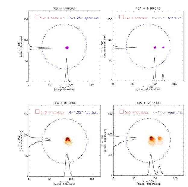
NUV images of point sources observed through the PSA (top) and BOA (bottom) using MIRRORA (left) and MIRRORB (right). The limits of each plot represent the 170 × 170 pixel image used by ACQ/IMAGE. Also shown are the COS aperture (blue circle of radius 1.25") and the 9 × 9 checkbox used by ACQ/IMAGE. Histograms show the AD and XD profiles. The pointing is typical of that expected after an ACQ/SEARCH, but before additional peak-ups.
-
COS Instrument Handbook
- Acknowledgments
- Chapter 1: An Introduction to COS
- Chapter 2: Proposal and Program Considerations
- Chapter 3: Description and Performance of the COS Optics
- Chapter 4: Description and Performance of the COS Detectors
-
Chapter 5: Spectroscopy with COS
- 5.1 The Capabilities of COS
- • 5.2 TIME-TAG vs. ACCUM Mode
- • 5.3 Valid Exposure Times
- • 5.4 Estimating the BUFFER-TIME in TIME-TAG Mode
- • 5.5 Spanning the Gap with Multiple CENWAVE Settings
- • 5.6 FUV Single-Segment Observations
- • 5.7 Internal Wavelength Calibration Exposures
- • 5.8 Fixed-Pattern Noise
- • 5.9 COS Spectroscopy of Extended Sources
- • 5.10 Wavelength Settings and Ranges
- • 5.11 Spectroscopy with Available-but-Unsupported Settings
- • 5.12 FUV Detector Lifetime Positions
- • 5.13 Spectroscopic Use of the Bright Object Aperture
- Chapter 6: Imaging with COS
- Chapter 7: Exposure-Time Calculator - ETC
-
Chapter 8: Target Acquisitions
- • 8.1 Introduction
- • 8.2 Target Acquisition Overview
- • 8.3 ACQ SEARCH Acquisition Mode
- • 8.4 ACQ IMAGE Acquisition Mode
- • 8.5 ACQ PEAKXD Acquisition Mode
- • 8.6 ACQ PEAKD Acquisition Mode
- • 8.7 Exposure Times
- • 8.8 Centering Accuracy and Data Quality
- • 8.9 Recommended Parameters for all COS TA Modes
- • 8.10 Special Cases
- Chapter 9: Scheduling Observations
-
Chapter 10: Bright-Object Protection
- • 10.1 Introduction
- • 10.2 Screening Limits
- • 10.3 Source V Magnitude Limits
- • 10.4 Tools for Bright-Object Screening
- • 10.5 Policies and Procedures
- • 10.6 On-Orbit Protection Procedures
- • 10.7 Bright Object Protection for Solar System Observations
- • 10.8 SNAP, TOO, and Unpredictable Sources Observations with COS
- • 10.9 Bright Object Protection for M Dwarfs
- Chapter 11: Data Products and Data Reduction
-
Chapter 12: The COS Calibration Program
- • 12.1 Introduction
- • 12.2 Ground Testing and Calibration
- • 12.3 SMOV4 Testing and Calibration
- • 12.4 COS Monitoring Programs
- • 12.5 Cycle 17 Calibration Program
- • 12.6 Cycle 18 Calibration Program
- • 12.7 Cycle 19 Calibration Program
- • 12.8 Cycle 20 Calibration Program
- • 12.9 Cycle 21 Calibration Program
- • 12.10 Cycle 22 Calibration Program
- • 12.11 Cycle 23 Calibration Program
- • 12.12 Cycle 24 Calibration Program
- • 12.13 Cycle 25 Calibration Program
- • 12.14 Cycle 26 Calibration Program
- • 12.15 Cycle 27 Calibration Program
- • 12.16 Cycle 28 Calibration Program
- • 12.17 Cycle 29 Calibration Program
- • 12.18 Cycle 30 Calibration Program
- • 12.19 Cycle 31 Calibration Program
- • 12.20 Cycle 32 Calibration Program
- • 12.21 Cycle 33 Calibration Program
- Chapter 13: COS Reference Material
- • Glossary