5.8 Fixed-Pattern Noise
The S/N of COS observations in CalCOS is improved through two techniques, flat fielding and coadding spectra taken at different central wavelengths or FP-POS settings. Flat fielding removes low-frequency variations on the detector by dividing the data by a high S/N flat-field response image. FP-POS exposures smooth out pixel-to-pixel detector variations by combining in wavelength space data taken at different positions on the detector.
5.8.1 COS Flat Fielding
The internal flat-field calibration system consists of two deuterium lamps and the flat-field calibration aperture (FCA). The system was designed such that light from the lamps follows nearly the same optical path as that from an external target. The FCA is placed near the usual location of the PSA, and the lamp beam illuminates the gratings and mirrors from this slightly offset position.
The deuterium lamps are not bright enough to map out the flat field at FUV wavelengths, so the FUV flats are constructed from on-orbit observations of bright white dwarfs. An image of the FUV detector using the deuterium lamp is shown in Figure 5.13. The light, vertical stripe is a shadow cast by a grid wire in front of the detector (Section 4.1.1). A detector dead spot and the hexagonal pattern of the fiber bundles in the micro-channel plate are also visible. Although significant structure is present in the FUV flats, it is reproducible and can be removed during data reduction.
Figure 5.13: Section of a Flat-Field Image for the FUV XDL.
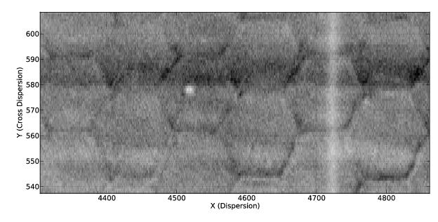
A section of the FUV flat field showing representative detector features and a grid wire (the light vertical stripe at a pixel position of 4720).
FP-POS settings (Section 5.8.2).Figure 5.14: Correcting Grid-Wire Shadows with Flat-Field Reference File.
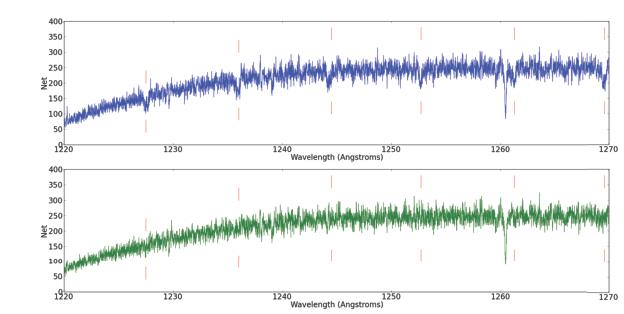
G130M FUVB exposure of the white dwarf WD0320-539 obtained at the original lifetime position. The upper (blue) spectrum contains grid-wire shadows (indicated by the vertical lines), which are corrected in the lower (green) spectrum.
FP-POS settings (see COS ISR 2023-11 for more details). To attain higher SNR ratios special analysis procedures, such as those described in Bagnuolo & Gies (1991, ApJ, 376, 266), and Lambert et al. (1994, ApJ, 470, 756) are required. Consult with your contact scientist for details.
Table 5.6: Maximum Achievable 50th percentile SNR for COS/FUV Spectroscopy.
| Grating | FUVA | FUVB |
|---|---|---|
Single | ||
G130M | 17.9 | 23.8 |
G160M | 14.9 | 20.4 |
G140L | 19 | - |
Combining 2 | ||
G130M | 22 | 27 |
G160M | 20 | 24 |
G140L | 23 | - |
Combining 3 | ||
G130M | 27 | 34 |
G160M | 25 | 31 |
G140L | 29 | - |
Combining 4 | ||
G130M | 32 | 40 |
G160M | 29 | 35 |
G140L | 36 | - |
Because the grid wires are oriented perpendicular to the spectrum, their effect on the data is relatively insensitive to the location of the spectrum in the cross-dispersion direction. Much of the remaining fixed-pattern noise depends strongly on the spectrum location, and will require considerably more effort to characterize and correct. The grid-wire flats have been shown to be independent of the y position on the detector, so they can be applied at all lifetime positions.
In addition to grid-wire shadows, grid-wire "impostors" were discovered in COS FUV data. The morphology of the impostors in the extracted spectra is similar overall to that of the grid-wire shadows. However, unlike the grid-wire shadows, the impostor features depend strongly on the y position on the detector. From the appearance of these features in the dark exposures, it was determined that the impostors are artifacts introduced by the geometric distortion correction. However, due to the way that the geometric distortion corrections are integrated into nearly every other aspect of calibration, this reference file cannot be changed quickly. Therefore, a 2D correction for the "impostors" has been incorporated into the FLATFIELD reference file until a fix to the geometric distortion correction can be fully investigated and tested. As a result CalCOS now corrects these features through the flat-field correction.
Comparison of extracted spectra at difference FP-POS and CENWAVE settings has revealed y-independent illumination variations on each detector segment. These variations are corrected in CalCOS by applying a low-order flat-field correction (L-flat) that has been incorporated into the FLATFIELD reference file. The L-flats applicable to the fourth lifetime position are shown in Figure 5.15, and an example of the improvement obtained using the L-flat is shown in Figure 5.16.
Figure 5.15: L-Flat Amplitudes for COS FUV.
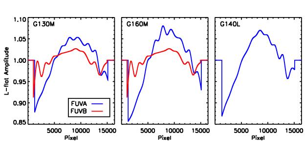
The amplitudes of the L-flats for the COS FUV A and B segments.
Figure 5.16: A Comparison of COS Spectra with and without the L-Flat Correction.
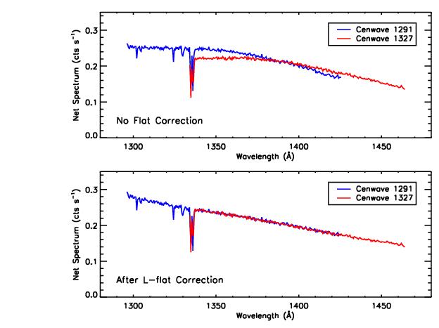
The top panel shows two COS spectra without the L-flat correction. The bottom panel shows the same two spectra with the L-flat correction.
Figure 5.17: Flat-Field Exposures for the NUV MAMA.
5.8.2 Use of Multiple FP-POS Settings
Fixed-pattern noise in the COS detectors limits the S/N that can be achieved in a single exposure to 15-25 per resolution element for the FUV and 50 for the NUV. To achieve higher S/N ratios one can obtain a series of exposures, each slightly offset in the dispersion direction, causing spectral features to fall on a different part of the detector. For STIS these motions are known as FP-SPLITs. For COS these motions are specified by the FP-POS optional parameter.
Four FP-POS offset positions are available: a nominal position (0), two positions toward longer wavelengths (−2 and −1), and one position toward shorter wavelengths (+1). Positions −2, −1, 0, and +1 are designated respectively as FP-POS=1, 2, 3, and 4. The nominal position, FP-POS=3, is the setting used to define the wavelength range associated with the grating central wavelengths (Table 5.3 and Table 5.4). In pipeline processing CalCOS creates individual calibrated spectra for each FP-POS position, then aligns and combines them into a merged spectral product, using only good-quality data at each wavelength.
The optical mechanism on which the grating is mounted is rotated by one step for each adjacent FP-POS position. The amount that a particular spectral feature moves in the dispersion direction on the detector is approximately 250 pixels per step for the FUV channel and 52 pixels for the NUV. The corresponding wavelength shifts for each grating are given in Chapter 13. There is a preferred direction for moving the grating mechanism. Overheads are reduced if FP-POS exposures are obtained in increasing order (see Section 9.5). When moving to a new grating or central-wavelength setting you may select any FP-POS position without paying an additional overhead penalty. Thus, the most efficient order is FP-POS=1, 2, 3, 4, as it requires no backward motion of the grating mechanism.
A wavelength calibration exposure will be obtained each time the FP-POS changes. For FLASH=YES exposures the time-since-last-grating-motion clock is not reset by an FP-POS movement. However, there will always be at least one lamp flash during each individual FP-POS exposure. For FLASH=NO exposures a separate wavelength calibration exposure will be taken for each FP-POS position change. Using all four FP-POS for each CENWAVE can be achieved by using the FP-POS=ALL parameter in APT for each CENWAVE or by spreading out the four FP-POS positions over multiple orbits within a visit for each CENWAVE or over multiple visits to the same target.
Please consult the COS 2025 website for rules and restrictions pertaining to the use of the G130M grating to reduce the impact of Ly-α airglow. Note that certain COS observing settings are disallowed for certain scenarios.
Requirements for Use of Multiple FP-POS Settings in the FUV
The use of multiple FP-POS positions for each CENWAVE setting of the COS FUV detector is required unless a strong scientific justification to do otherwise is provided in the Phase I. (There is no such requirement for NUV observations.) Using multiple FP-POS positions improves the limiting S/N and minimizes the effects of flat-field artifacts. The use of multiple FP-POS positions is especially important for the FUV detector as the fixed pattern noise is larger and more poorly characterized than that of the NUV detector.
Since this simple shift-and-add technique significantly improves the signal-to-noise ratio of the resulting spectrum, and will extend the lifetime of the COS FUV detector, the use of multiple FP-POS for each CENWAVE setting is required for FUV science observations. Proposers using the FUV channel of COS, but who do not intend to use all four FP-POS settings for each CENWAVE setting, must justify their observing strategy in their Phase I proposals. (Under the COS 2025 rules, the G130M/1291 setting has only two FP-POS for SEGMENT = B or BOTH; both FP-POS must be used in this case.) A modest reduction in observational overheads will not normally be considered sufficient justification for not using all four FP-POS settings, unless using G160M. Starting in Cycle 33, users of G130M are permitted to use fewer than 4 FP-POS based on the S/N limits described in Section 9.5.1. The exposure times per FP-POS should be as equal as practical, but if there are multiple orbits for a target, the four FP-POS may be distributed among the orbits in such a way that FP-POS changes during an orbit are minimized.
-
COS Instrument Handbook
- Acknowledgments
- Chapter 1: An Introduction to COS
- Chapter 2: Proposal and Program Considerations
- Chapter 3: Description and Performance of the COS Optics
- Chapter 4: Description and Performance of the COS Detectors
-
Chapter 5: Spectroscopy with COS
- 5.1 The Capabilities of COS
- • 5.2 TIME-TAG vs. ACCUM Mode
- • 5.3 Valid Exposure Times
- • 5.4 Estimating the BUFFER-TIME in TIME-TAG Mode
- • 5.5 Spanning the Gap with Multiple CENWAVE Settings
- • 5.6 FUV Single-Segment Observations
- • 5.7 Internal Wavelength Calibration Exposures
- • 5.8 Fixed-Pattern Noise
- • 5.9 COS Spectroscopy of Extended Sources
- • 5.10 Wavelength Settings and Ranges
- • 5.11 Spectroscopy with Available-but-Unsupported Settings
- • 5.12 FUV Detector Lifetime Positions
- • 5.13 Spectroscopic Use of the Bright Object Aperture
- Chapter 6: Imaging with COS
- Chapter 7: Exposure-Time Calculator - ETC
-
Chapter 8: Target Acquisitions
- • 8.1 Introduction
- • 8.2 Target Acquisition Overview
- • 8.3 ACQ SEARCH Acquisition Mode
- • 8.4 ACQ IMAGE Acquisition Mode
- • 8.5 ACQ PEAKXD Acquisition Mode
- • 8.6 ACQ PEAKD Acquisition Mode
- • 8.7 Exposure Times
- • 8.8 Centering Accuracy and Data Quality
- • 8.9 Recommended Parameters for all COS TA Modes
- • 8.10 Special Cases
- Chapter 9: Scheduling Observations
-
Chapter 10: Bright-Object Protection
- • 10.1 Introduction
- • 10.2 Screening Limits
- • 10.3 Source V Magnitude Limits
- • 10.4 Tools for Bright-Object Screening
- • 10.5 Policies and Procedures
- • 10.6 On-Orbit Protection Procedures
- • 10.7 Bright Object Protection for Solar System Observations
- • 10.8 SNAP, TOO, and Unpredictable Sources Observations with COS
- • 10.9 Bright Object Protection for M Dwarfs
- Chapter 11: Data Products and Data Reduction
-
Chapter 12: The COS Calibration Program
- • 12.1 Introduction
- • 12.2 Ground Testing and Calibration
- • 12.3 SMOV4 Testing and Calibration
- • 12.4 COS Monitoring Programs
- • 12.5 Cycle 17 Calibration Program
- • 12.6 Cycle 18 Calibration Program
- • 12.7 Cycle 19 Calibration Program
- • 12.8 Cycle 20 Calibration Program
- • 12.9 Cycle 21 Calibration Program
- • 12.10 Cycle 22 Calibration Program
- • 12.11 Cycle 23 Calibration Program
- • 12.12 Cycle 24 Calibration Program
- • 12.13 Cycle 25 Calibration Program
- • 12.14 Cycle 26 Calibration Program
- • 12.15 Cycle 27 Calibration Program
- • 12.16 Cycle 28 Calibration Program
- • 12.17 Cycle 29 Calibration Program
- • 12.18 Cycle 30 Calibration Program
- • 12.19 Cycle 31 Calibration Program
- • 12.20 Cycle 32 Calibration Program
- • 12.21 Cycle 33 Calibration Program
- Chapter 13: COS Reference Material
- • Glossary