3.3 Structure of calacs
The calacs package consists of five tasks listed in Table 3.2. These tasks, available in the HSTCAL package, are automatically called by calacs, but each may be run separately via acstools. We provide additional details and relevant calacs code examples in the ACS/WFC Image Reduction Jupyter notebook.
Table 3.2: Tasks in the calacs Pipeline
acsccd | CCD specific calibrations, except CTE corrections |
acscte | CTE corrections for WFC images1 |
acsrej | Cosmic ray rejection task |
acs2d | Basic MAMA and CCD calibrations |
acssum | Repeated observations summing task for MAMA data |
1 CTE loss correction is available for a WFC 2K subarray of the old format or any WFC subarray of the new format. The subarray formats were switched during Cycle 24, in October 2016. However, due to the complexity of bias de-striping the post-SM4 WFC subarray images, PCTECORR is set to OMIT by default in the pipeline for all subarrays. To perform CTE pixel-based correction for an eligible WFC subarray, please set PCTECORR to PERFORM in the image header and use the acs_destripe_plus task in acstools. See also Example 5 in Section 3.5.2.
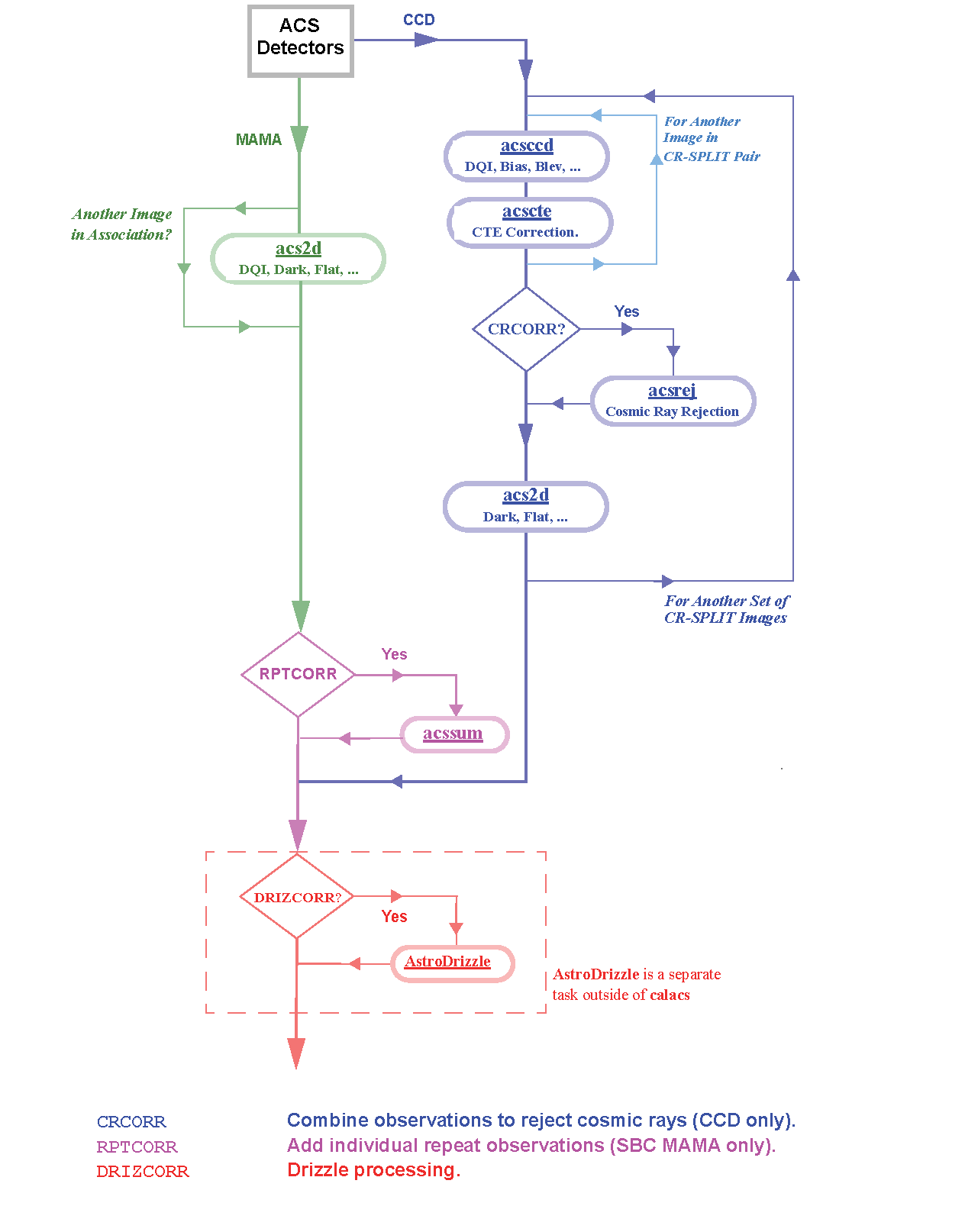
The flow of data through the ACS calibration pipeline and the decisions made while working with associated data are shown in Figures 3.1, 3.2, and 3.3. They are also outlined below with the calacs tasks and functions in parenthesis.
- Flag known bad pixels and A-to-D saturated pixels in the data quality (DQ) array. (acsccd/doDQI or acs2d/doDQI)
- Subtract the bias image (CCD only). (acsccd/doBias)
- Multiply by gain to convert DN to electrons. (acsccd/toElectrons or acs2d/toElectrons)
- Subtract the bias level, which is determined from overscan regions (CCD only). For post-SM4 full frame WFC images, also correct for bias shift, cross-talk, and striping. (acsccd/doBlev)
- Flag full-well saturated pixels in the data quality (DQ) array (CCD only). (acsccd/doFullWellSat)
- Flag sink pixels in the DQ array of WFC images (CCD only). (acsccd/doSink)
- Calculate a noise model for each pixel and record it in the error (ERR) array. (acsccd/doNoise or acs2d/doNoise)
- Perform pixel-based CTE corrections for applicable WFC images (CCD only). (acscte)
- Combine images, with cosmic ray rejection, for "CR-SPLIT" and repeated exposures (CCD only). (acsrej)
- Perform global linearity corrections (MAMA only). (acs2d/doNonLin)
- Scale and subtract the dark image, and calculate the mean dark value (CCD only, by default). (acs2d/doDark)
- Scale and subtract the post-flash image, if required (CCD only). (acs2d/doFlash)
- Divide the image by the flat field. (acs2d/doFlat)
- Apply shutter shading correction (CCD only). (acs2d/doShad)
- Calculate photometry header keywords for flux conversion (except for slitless spectroscopy modes). (acs2d/doPhot)
- Calculate image statistics; these values are stored in calibrated data headers. (acs2d/doStat)
- Sum images from repeated sub-exposures in an ACS/SBC exposure (MAMA only). (acssum)
Calibrated flt.fits/flc.fits images from "CR-SPLIT" exposures, repeated sub-exposures, "POS TARG" exposures, or dither "PATTERN" exposures may be combined using AstroDrizzle. Please refer to the DrizzlePac website for information regarding drizzling the images.
As indicated in Figure 3.1, calibration tasks that are detector-specific (like acsccd for WFC data only) have been separated from tasks that can process both detectors (such as acs2d).
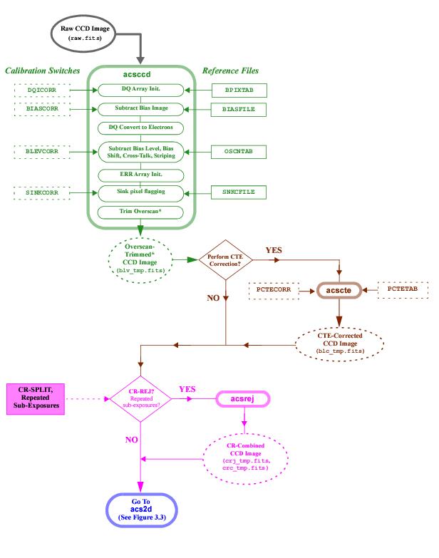
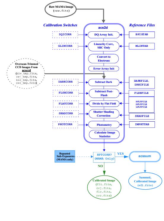
The initial processing performed on CCD data alone is shown in Figure 3.2. Reference files appropriate for each processing step and the calibration switches controlling them are also given beside the name of the task they control. The output (overscan-trimmed image) from acsccd is then sent through acscte (if appropriate) and acs2d as shown in Figure 3.3.
Processing of raw MAMA data begins with acs2d, which initializes the error and data quality arrays (a step that was performed earlier for CCD data) and applies linearity corrections.


