4.1 Read Noise and A-to-D Conversion
HRC has been unavailable since January 2007. Information about the HRC is provided for archival purposes.
4.1.1 Read Noise
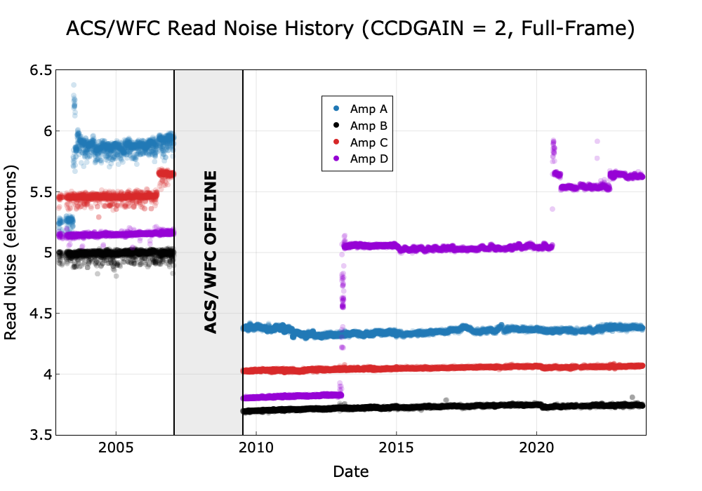
Read noise is an irreducible contribution to the total error budget. It is linked to the readout process and there are no reduction steps that can minimize or remove it. The influence of read noise is minimized by reducing the number of pixels in the photometry aperture and by subdividing the total exposure time into the minimum number of component readouts while still ensuring adequate cosmic-ray rejection, hot-pixel removal, and pixel-phase sampling. Aside from differences between the amplifiers on WFC, read noise is independent of position on the detector. Tables 4.1, 4.2, and 4.3 show gain and read noise values of the four WFC amplifiers and the single HRC amplifier for different time periods. Figure 4.1 illustrates the history of the amplifier-based read noise (in electrons) for ACS/WFC since 2003. The read noise values are steady to 1% or better, except for five discrete events during the ACS lifetime. Two of these events were associated with ACS electronics changes: 1) a jump in the amplifier C noise after the 2006 failure of the Side 1 electronics, and 2) the overall drop in read noise once the ACS was repaired during SM4 in 2009. The three other events, read noise increases in amplifier A (June 2003) and amplifier D (January/February 2013 and July 2020), have been ascribed to radiation damage on the detector (ACS TIR 2013-02, ACS TIR 2020-011). In each case, fluctuating read noise levels typically stabilized after subsequent anneals. Amplifier D read noise has been slightly unstable since the jump in July 2020, fluctuating between ~5.55 and ~5.65 e– with brief, higher excursions.
Table 4.1: WFC Amplifier Gain and Read Noise After Installation of the CEB-R (Valid After May 2009). Values apply to dual-slope integrator mode of pixel sampling.
| CCD | Amp | Gain (e¯/DN) 0.5 1.0 1.4 2.0a | Read Noise (e¯) | ||||||
WFC1 | A | 0.53 | 1.03 | 1.45 | 2.020 | 3.92 | 4.05 | 4.28 | 4.35 |
WFC1 | B | 0.50 | 0.96 | 1.36 | 1.886 | 3.24 | 3.36 | 3.61 | 3.75 |
WFC2 | C | 0.53 | 1.03 | 1.45 | 2.017 | 3.54 | 3.69 | 3.95 | 4.05 |
WFC2 | D | 0.53 | 1.02 | 1.45 | 2.011 | 3.31b | 3.43b | 3.71b | 5.65c |
a Default Gain.
b May not be valid after July 24, 2020.
c Valid after July 24, 2020.
d The 1σ scatter in the read noise is 0.01–0.02 electrons.
Table 4.2: CCD Gain and Read Noise Operated Under Side 1 of Original CEB (March 2002 to June 2006)
| CCD | Amp | Gain (e¯/DN) 1 2a 4 | Read Noise (e¯) 1 2a 4 | ||||
WFC1 | A | 1.000 | 2.002 | 4.01 | 5.57 | 5.84 | – |
WFC1 | B | 0.972 | 1.945 | 3.90 | 4.70 | 4.98 | – |
WFC2 | C | 1.011 | 2.028 | 4.07 | 5.18 | 5.35 | – |
WFC2 | D | 1.018 | 1.994 | 4.00 | 4.80 | 5.27 | – |
HRC | C | 1.163 | 2.216 | 4.235 | 4.46 | 4.80 | 5.86 |
a Since Cycle 14 (under Side 1 operations), the default gain has been GAIN = 2. Prior to this, GAIN = 1 was the default.
Table 4.3: CCD Gain and Read Noise Operated Under Side 2 of Original CEB (July 2006 to January 2007)
| CCD | Amp | Gain (e¯/DN) 1 2 a 4 | Read Noise (e¯) 1 2a 4 | ||||
WFC1 | A | 1.000 | 2.002 | 4.01 | 5.29 | 5.62 | – |
WFC1 | B | 0.972 | 1.945 | 3.90 | 4.45 | 4.74 | – |
WFC2 | C | 1.011 | 2.028 | 4.07 | 5.03 | 5.34 | – |
WFC2 | D | 1.018 | 1.994 | 4.00 | 4.55 | 4.89 | – |
HRC | C | 1.163 | 2.216 | 4.235 | 4.36 | 4.82 | 5.44 |
a Default Gain.
4.1.2 A-to-D Conversion
The analog information (electrons) accumulated in the CCD is converted into data numbers (DNs) by the analog-to-digital converter (ADC). Both ACS CCD cameras employ 16-bit ADCs, which can produce a maximum of 216 −1 = 65,535 DN. If the gain conversion factor g is expressed in e¯/DN, the largest number of electrons representable by these ADCs is given by g × 216, also known as the A-to-D saturation limit. For gain = 2.0, pixels should not suffer ADC saturation before full well saturation. A recent study (ACS ISR 2020-03) has found that post-SM4 A-to-D saturated pixels can actually have lower values than expected. The CALACS pipeline now flags all post-SM4 pixel values above 64,000 DN as A-to-D saturated. More details on the A-to-D saturation limit can be found in Section 4.7.4.
The analog-to-digital converter produces only discrete output levels. This means that a range of analog inputs can produce the same digital output. This round-off error is called quantizing noise. It can be shown that quantizing noise QN is constant for a given gain (g) setting when expressed in DN (Janesick 2001):
| \mathrm{QN}(\mathrm{DN}) = 12^{-1/2} = 0.2888675. |
Quantizing noise can be converted into noise electrons as:
| \mathrm{QN}(e^-) = 0.288675 \cdot g. |
The measured read noise (RN; reported in Tables 4.1, 4.2, and 4.3) is the quadrature sum of this quantizing noise and the intrinsic read noise (IRN) associated with a particular readout amplifier:
| \mathrm{RN} = (\mathrm{IRN}^2 + (0.288675 \cdot g)^2)^{1/2} |
1 Technical Instrument Reports (TIRs) are available upon request.
