4.4 Flat-Field Reference Files
HRC has been unavailable since January 2007. Information about the HRC is provided for archival purposes.
The flat-field reference files currently in use by the ACS calibration pipeline have been derived via different methods, depending on the detector and the filter used. These "LP-flats" are a combination of a "P-flat," which accounts for the pixel-to-pixel variations in sensitivity, and of an "L-flat," which models the low-frequency variations in sensitivity over the detector field of view. CCD LP-flats were created in the laboratory using an external illumination source and were corrected in-flight from dithered stellar observations of 47 Tucanae. For the SBC, P-flats were derived from in-flight internal lamp exposures, while the SBC L-flats were derived from dithered NGC 6681 exposures. (Flat field files in CRDS have the suffix pfl.fits despite being combinations of L and P flats. See doFlat in Section 3.4.4.)
4.4.1 Ground Flats (P-flats)
CCDs
In early 2001, flat-field images for the ACS were produced in the laboratory (see ACS ISR 2001-11) using the Refractive Aberrated Simulator/Hubble Opto-Mechanical Simulator (RAS/HOMS). The RAS/HOMS is a HST simulator capable of delivering OTA-like external monochromatic point source and broad-band full field illumination above its refractive cutoff wavelength of ~3500 Å.
Because the RAS/HOMS optics are opaque below 3500 Å, flats for the UV filters F330W and F344N (see ACS ISR 2003-02 and ACS ISR 2005-12) were created using in-flight observations of the bright Earth (see Section 4.4.4). Unfortunately, red leaks in F220W and F250W are so large that the out-of-band light dominates earth-flat observations, and the lab flats made with the deuterium lamp illumination are superior to the Earth flats for these two filters.
A total signal of about 100,000 electrons per pixel is required for each flat field to avoid degrading the intrinsic pixel-to-pixel rms response of < 1% for the ACS CCD detectors. The flats are normalized by dividing by the average number of counts in the central 1% of the frame. In the case of full WFC frames, the WFC2 images are divided by the WFC1 central value in order to preserve the overall sensitivity difference between the two CCD chips across the ~50 pixel gap that separates the two independent pieces of the WFC detector. For small filters that cover just part of one quadrant of the WFC (i.e., F892N, polarizers), flats were masked to unity below 90% of the central value of the data, so that no flat-field correction is done on the scattered light outside the physical edge of the filter.
More information on the HRC and WFC ground flats can be obtained from ACS ISR 2001-11 for the standard filters, polarizers, and coronagraph, from ACS ISR 2002-01 for the ramp filters, and from ACS ISR 2002-04 for the prism and grism. The stability of P-flats is tested in each cycle. Please see ACS ISR 2007-01 for more information about the stability of P-flats after the cooldown to −81°C in 2006. Observations made during SMOV SM4 show that WFC P-flats are stable.
MAMA
Flat fields for the full set of SBC filters were also taken in the laboratory (ACS ISR 1999-02), but were later replaced with in-flight observations using the internal deuterium lamp (ACS ISR 2005-04 and ACS ISR 2016-02). Analysis of original laboratory flats indicates that the P-flat response is independent of wavelength, so the F125LP lamp flat was used for all filters. The internal lamp illumination does not simulate the OTA optics and, therefore, is useful only for correcting the pixel-to-pixel detector response. In order to accurately model the low-frequency variations in sensitivity, which may depend on wavelength, dithered star field observations were required. (See Section 4.4.2 for a discussion of the SBC L-flats.) A study of the changes in the SBC P-flat finds that random pixel-to-pixel fluctuations have been small, but there are changes in the larger-scale fringing patterns that warrant the production of a new P-flat in the near term. In addition, the internal deuterium lamp is degrading with time, and currently produces about 65% of the original brightness (ACS ISR 2016-02).
4.4.2 L-flats
CCDs
The large scale uniformity of the WFC and HRC detector response, as initially shown in the CCD laboratory flats, has been improved in-flight by using multiple dithered pointings of stars in 47 Tucanae. By placing the same stars at different locations on the detector and measuring relative changes in brightness, low frequency spatial variations in the response of each detector have been measured (including the pixel-area corrections discussed in Section 3.4.4). Photometric errors of ±3% to ±9%, corner-to-corner, have been found in the original WFC and HRC laboratory flat fields (see ACS ISR 2002-08). The derived L-flats are based on a 4th-order polynomial fit and are shown in Figure 4.17 and Figure 4.18 for WFC and HRC, where white indicates that the photometry produced using the laboratory flats is too faint with respect to the true stellar magnitude, and black indicates that the photometry is too bright. There is a continuous gradient in the L-flat correction along the diagonal of the detector which corresponds to the axis of maximum geometric distortion variation.
L-flats were determined from in-flight observations using filters F435W, F555W, F606W, F775W, F814W, and F850LP for both the WFC and HRC. The HRC study included two additional filters: F475W and F625W. The L-flat correction for the remaining filters was derived by using linear interpolation as a function of wavelength. The pivot wavelength of each filter was used for the interpolation, where the resulting L-flat is equal to the weighted average of the L-flat for the two filters nearest in wavelength. Due to red leaks in the F220W and F250W HRC filters, no L-flat correction has been applied, and errors in the flats of ±2% to ±4%, corner-to-corner, are expected for these filters. For a detailed discussion of ACS L-flat corrections, refer to ACS ISR 2002-08. For a discussion of the mathematical algorithm used to derive the L-flats, refer to ACS ISR 2003-10.
Following the recovery of ACS with Side 2 electronics in July 2006, the temperature set-point was lowered from a nominal value of −77°C to −81°C for the WFC in order to minimize impacts of the continuously growing hot pixels. The required L-flat changes ranged from ~0.6% peak-to-peak at F435W to 0.15% at F814W (see ACS ISR 2006-06). Revised L-flats were created and delivered, post-cooldown, in July 2006. Since then, they have been monitored and derived again using more data as described in ACS ISR 2020-01.
MAMA
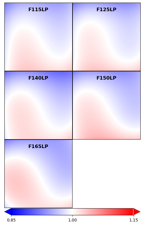
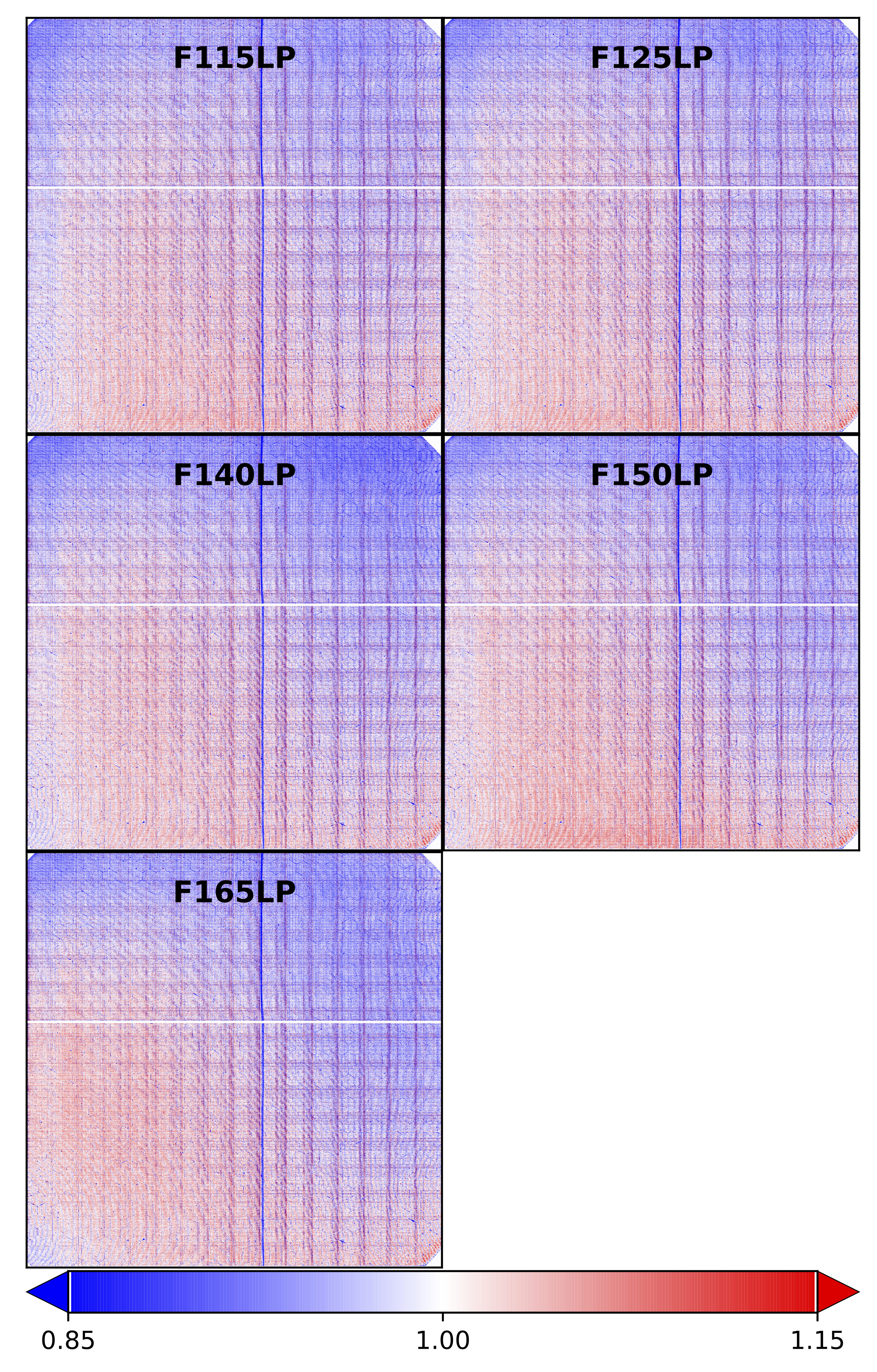
As was done for the CCDs, the SBC L-flats were derived using dithered star-field observations. Instead of 47 Tucanae, however, the UV-bright globular cluster NGC 6681, which is rich in blue horizontal branch stars, was selected. This work is summarized in ACS ISR 2005-13 and ACS ISR 2019-04. The required corrections to the in-flight lamp flats are given in Figure 4.19 and range by ±15%, depending on wavelength. Since insufficient observations with the F122M filter exist, this L-flat is simply a copy of the F115LP filter correction. Six new flat fields have been delivered for use in the calibration pipeline, and the resulting photometric accuracy is now ±2.5 % for F115LP, F122M, F125LP, F140LP, and F150LP, and ±3.3 % for F165LP.
Figure 4.17: WFC Low Frequency (L-flat) Flat-Field Corrections Required for the Laboratory Data
While the pixel-to-pixel (P-flat) structure of the laboratory flats is robust, a low frequency correction is required to achieve uniform detector response. This correction ranges from ±5% for the F555W filter to ±9% for the F850LP filter.
Figure 4.18: HRC Low Frequency (L-flat) Flat-Field Corrections Required for the Laboratory Flats
This correction ranges from ±3% for the F555W filter to ±6% for the F850LP filter.
Figure 4.19: SBC Low Frequency (L-flat) Flat-Field Corrections Required for the In-flight Deuterium Lamp Data
The inferred L-flat corrections were multiplied by the corresponding P-flats, and the resulting LP-flats are used for flat correction in the calibration pipeline. Users may verify their data have been calibrated with the most recent flat field reference files by checking the HST Calibration Reference Data System (CRDS) webpage.
Figure 4.20 shows the WFC LP-flats for several broad-band filters. Note that on the sky, a gap of ~50 pixels exists between the top and bottom chips that is not shown here. The central donut-like structure is due to variations in chip thickness (see ACS ISR 2003-06) and is dependent on wavelength. Pixels in the central region, for example, are less sensitive than surrounding pixels in the blue F435W filter, and more sensitive in the red F850LP filter.
For the HRC, LP-flats for the same broad-band filters are shown in Figure 4.21. The donut-like structure seen in the WFC response is not found in the HRC flats. The small dark rings are shadows of dust on the CCD window (see Section 4.5.1). The large dust mote seen in the WFC F606W flat is due to dust on the F606W filter. That portion of the filter is not "seen" by the HRC detector.
Because of the observed changes in P-flats discussed in the previous section, two versions of the LP-flat exist in the pipeline for each SBC filter. The set used for observations after 2007 are presented in Figure 4.22.
Because of geometric-distortion effects, the area of the sky intercepted by the detector pixels can vary across the detector; therefore, observations of a constant surface brightness object will have count rates per pixel that vary over the detector, even if every pixel has the same sensitivity. In order to produce images that appear uniform for uniform illumination, the observed flat fields include the effect of the variable pixel area across the field. A consequence of dividing by these flat fields is that two stars of equal brightness do not have the same total counts after the flat-fielding step. Therefore, flat-fielded images (flt.fits/flc.fits and crj.fits/crc.fits) must be multiplied by the effective pixel area map before extracting point source photometry. (See Section 5.1.3.) Alternately, users may use images processed by AstroDrizzle (with suffix drz.fits/drc.fits) where a geometric distortion solution has been applied to correct all pixels to equal areas. In drizzled images, photometry is correct for both point and extended sources.
Accuracy of pipeline flats can be verified using a variety of complementary methods. Section 4.4.2 explained how follow-up observations of the same stellar field can be used to verify the derived L-flat corrections. Alternately, observations of the bright Earth can provide a uniform flat-field source for the complete OTA optical complement and incorporate both the low frequency L-flat and the high frequency pixel-to-pixel P-flat response. Earth flats are described in Section 4.4.4. For most filters, the flats agree to within ~1%, except for the interpolated L-flat filters which usually agree to within ~2%.
The third method for verifying the ACS pipeline flats is with sky flats. These can be made by filtering and summing many observations of sparse fields. Sky flats have been created for a few of the most frequently used broad-band WFC filters and are discussed in detail in Section 4.4.5. The sky flats are generally similar to LP-flats at the 1% level, in accordance with the results of the previous two methods. While the WFC can show residuals in the central donut-region which are as large as 2%, these are most likely due to differences in the color of the spectrum of the sky from that of the bright globular cluster stars used for the L-flat determination.
To summarize, the pipeline LP-flats were created by correcting the pixel-to-pixel flats by low-frequency corrections derived from dithered stellar observations. For the most used modes, the flats are accurate to better than 1% across the detector.
Figure 4.20: WFC Flat Fields
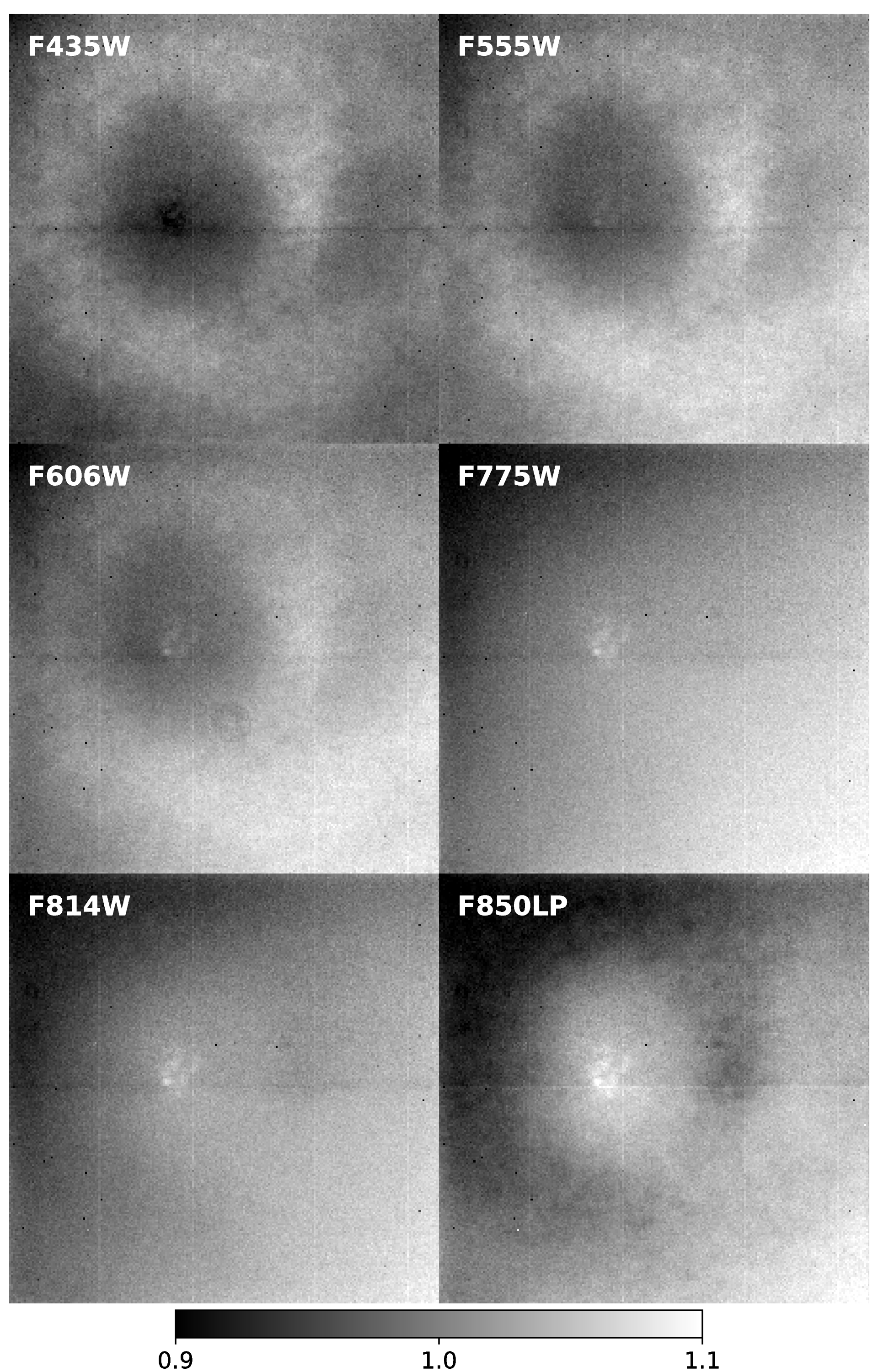
Figure 4.21: HRC Flat Fields
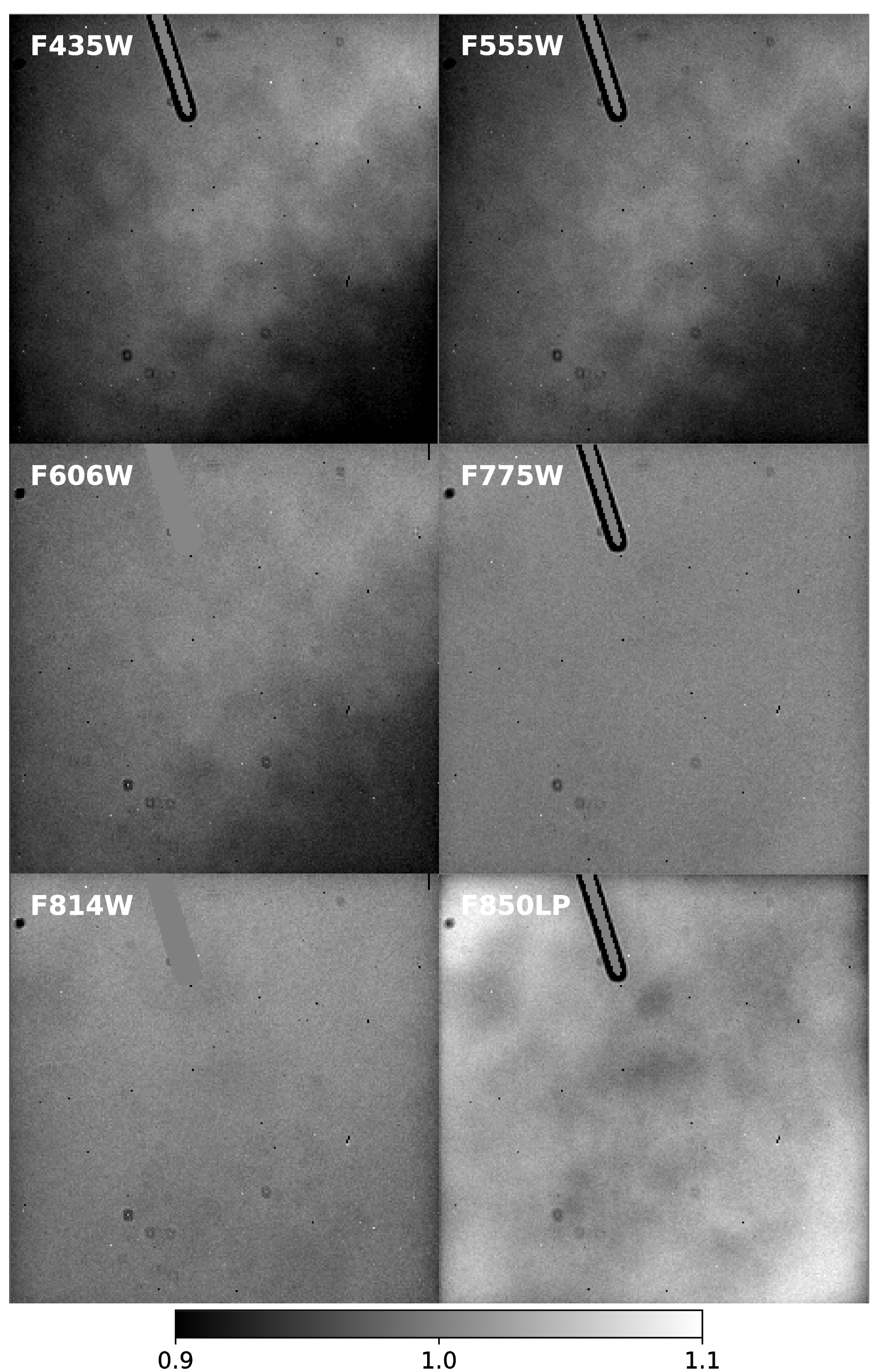
Figure 4.22: SBC Flat Fields
4.4.4 Earth Flat Verification for the HRC
Because the RAS/HOMS optics are opaque below 3500 Å (see Section 4.4.1), flat fields for the HRC UV filters were created using in-flight observations of the bright Earth. The Earth is a poor flat-field source at optical wavelengths because structure in the cloud cover can cause streaking in the flat. However, HRC modes that utilized the F220W, F250W, F330W, and F344N were immune to streaks because of the large optical depth down to the tropospheric cloud layers. The bright Earth then provided a uniform flat-field source for the complete OTA+HRC optical complement.
The required calibration flats, which incorporate both the low frequency L-flat and the high frequency pixel-to-pixel P-flat response, can be easily produced from these observations. Unfortunately, the red leaks in F220W and F250W are so large that the out-of-band light dominated, and the lab flats made with the deuterium lamp illumination (see ACS ISR 2001-11 for details) are superior to the observed Earth flats for the modes that included these two filters. Because no L-flat correction has been applied, errors in the flats of ±2 % to ±4%, corner-to-corner, are expected for these filters. HRC F330W and F344N pipeline flats, on the other hand, are defined entirely by Earth flat data (see ACS ISR 2003-02 and ACS ISR 2005-12). With ~20−30 observations, each over the course of three years, these flats have very high signal-to-noise and showed repeatability to much better than the required 1% accuracy.
HRC Earth flats at wavelengths longward of 4000 Å often showed streaking and non-uniformities from clouds or the terminator. However, a number of the images are free from these defects and provided an independent verification of the stellar L-flat correction technique at visible wavelengths. Unfortunately, WFC Earth flats suffer from a shutter light leak, and the Earth limb is too bright for SBC observations.
Several hundred observations of the bright Earth were obtained using the full set of HRC standard filters (ACS ISR 2005-12). In general, the pipeline flat fields are confirmed to a precision of ~1%, validating the stellar L-flat corrections. The "interpolated" L-flats are not significantly worse than the L-flats derived from the Earth observations (see Section 4.4.2). One exception is the F550M filter which shows a total deviation of more than 2%. Other exceptions are the four longest wavelength HRC filters which show large systematic differences with the pipeline flats. These differences appear to be caused by stray light originating from the detector surface, where most of the long wavelength photons were reflected and then scattered back from nearby focal plane structures. Any filter transmitting at these long wavelengths would have seen the extra pattern from this light, though the strength of the additional stray light is proportional to the total flux of the source. Thus, for large diffuse objects that fully illuminated the detector, these Earth flats are more appropriate for calibration than the existing pipeline flats, which are appropriate for point sources.
4.4.5 Sky Flats for the WFC
The ACS team has made use of the extensive imagery from the Cycle 13 GOODS survey (Programs 9425 and 9583; PI M. Giavalisco) to construct high signal-to-noise sky flats. These sparsely populated, high Galactic latitude exposures have relatively uniform sky that can be stacked to further quantify the pixel-to-pixel variation of the instrumental response in the WFC F606W, F775W, and F850LP filters with some 50−70 images apiece.
The sky flats were created by median-combining the pipeline-reduced flt.fits files after removing cosmic rays and masking all of the sources. Because the GOODS data contained 2−4 dithers at each pointing, masking was necessary to eliminate the high values at each pixel. In addition, before combining, each image was inspected for scattered light artifacts.
Because sky flats are created from the pipeline calibrated flt.fits files, any flat-field signatures that are not in the pipeline flats should appear in the ratio. The combined sky flat in each filter was box-medianed for comparison to the corrected ground flat. The resulting ratios of pipeline to sky flats show variations across the field of view of < 2% for each of the three filters. The sky flats independently created from the two separate GOODS fields, showed excellent agreement (< 1%) for all three filters.
Parallel imaging data from the HST Frontier Fields campaign (Lotz et al. 2017) have been used to compute sky flats for the ACS/WFC detector in order to verify the accuracy of the current set of flat field reference files. In F606W and F814W, the sky flats show spatial residuals 1% or less. These residuals are similar in shape to the WFC flat field 'donut' pattern seen in Figure 4.20. Constructing an accurate sky flat for the F435W filter is more problematic, since the sky background is much lower at this wavelength and detector artifacts dominate the residuals. Point source photometry of HST photometric standards positioned across the WFC detector shows that the F435W flat is consistent to ~1% for a red standard, but shows deviations of ~3% across the field of view for a bluer white dwarf standard (ACS ISR 2017-09).