4.2 Bias Issues
HRC has been unavailable since January 2007. Information about the HRC is provided for archival purposes.
4.2.1 Bias Calibration
The calacs pipeline performs the bias correction in two steps (see Section 3.4.1):
- doBias: a "superbias" reference image is subtracted from the science image to remove the fixed bias structure and dark current accrued during readout (ACS ISR 2014-02, ACS ISR 2017-13 and ACS ISR 2020-04). The superbias, constructed from individual bias frames obtained three times a week, samples the fixed bias structure at a high signal-to-noise ratio and is free of cosmic ray artifacts. This calibration step is applied to the image before its conversion to units of electrons, so the superbias is in units of DNs.
- doBlev: this step subtracts the bias level from the image, after the image has been converted from DNs to electrons. For pre-SM4 data, the bias level is fitted from the physical overscan, and is subtracted from the science data. For post-SM4 data, additional steps are required to remove the bias level and other effects, such as bias shift, striping, and cross-talk.
WFC Bias Level Determination
Each quadrant of the WFC focal plane (A & B for WFC1, C & D for WFC2) has two overscan regions: a 24 pixel-wide leading physical pre-scan in columns 1–24 for amplifiers A & C, and columns 4121–4144 for amplifiers B & D, and a 20 row-wide virtual overscan in rows 2049–2068. The physical pre-scan is produced by 24 extra pixels in the CCDs' serial registers between the readout amplifiers and the imaging region of the CCD. The virtual overscans are obtained by over-clocking the last rows in the imaging regions of each CCD 20 times.
After each vertical row shift, the bias level requires some time to reach its nominal level. The bias levels in the first 18 columns of the physical pre-scans associated with each WFC amplifier decay quasi-exponentially to their nominal levels. The bias levels in the imaging areas of the CCDs can be safely measured using the six columns of the physical pre-scans adjacent to the imaging areas, i.e., columns 19–24 for amplifiers A & C, and columns 4121–4126 for amplifiers B & D. This information can be found in the columns BIASSECTA1/2 and BIASSECTB1/2 in the OSCNTAB.
The virtual overscan is not used to estimate the bias level. This region exhibits large scale structure that is quadrant- and gain-dependent. Moreover, this region can be contaminated by deferred charge due to degradation in the parallel charge transfer efficiency.
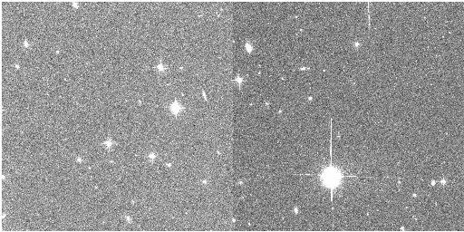
The WFC bias frames show small differences between the bias levels of the physical pre-scans and the imaging region of the CCD (Sirianni et al. 2002 and ACS ISR 2004-07). These bias offsets vary from amplifier to amplifier and can be as large as 3.5 DN. If these offsets were constant, superbias subtraction (doBias) would remove any differences between the pre-scans and the imaging region. Unfortunately, the offsets show random variations of about 0.3 DN that are possibly caused by interference between the WFC integrated electronics module and the telescope and/or other science instruments. The accuracy of the bias level subtraction in a single quadrant is limited by this random effect. Consequently, sky background levels often appear discontinuous across the boundaries of adjacent image quadrants after calacs processing (Figure 4.2). Automated photometry of point or extended sources that span the quadrant boundaries should therefore be considered suspect. In such cases, it is recommended to measure and subtract the sky-background levels in each quadrant separately.
Figure 4.2: Calibrated WFC1 Image Showing the Quadrant-to-Quadrant Jump
Post-SM4 WFC Bias Gradient
Since Servicing Mission 4 (SM4 in 2009), the WFC bias frames exhibit two-dimensional spatial gradients with amplitudes of 5-10 DN within each image quadrant (Figure 4.3). These gradients have been stable since SM4 (ACS ISR 2025-03), and so they are completely removed (along with other fixed pattern noise) in the doBias step of calacs. These gradients are characteristics of the dual-slope integrator (DSI) implemented in the replacement CCD electronics to reduce the noise incurred during pixel sampling. The gradients are mainly caused by slow drifts of the bias reference voltages during and after the readout of each row of pixels.
These gradients were not produced by the pre-SM4 CCD electronics, which used the clamp-and-sample technique of pixel sampling. The replacement electronics also offer the clamp-and-sample option and, consequently, gradient-free biases, but this option increases the read noise of the images by about 0.5-1.0 e¯. For this reason, the DSI is the default mode for post-SM4 WFC operations, while the clamp-and-sample is unsupported.
Figure 4.3: Bias Gradients Seen Within Each Image Quadrant in the WFC Superbias (in Units of Counts) after SM4
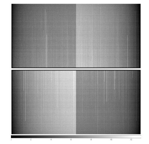
Figure 4.4: A Side-by-Side Comparison of the Same Image Section in a Single Bias (Left) and a Superbias That Has Not Been Corrected for Bias Striping (Right), from Late August 2009
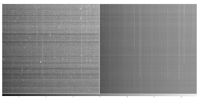
The linear stretch is identical, and is equivalent to ±3 σ of the single bias. The local pixel-to-pixel noise (including both read noise and striping noise) of the superbias, which comprises 16 biases (including the one shown on the left) is a factor of ~3.6 times lower than the noise level of the single bias.
Post-SM4 WFC Bias "Striping"
The ACS CCD Electronics Box Replacement includes a SIDECAR Application-Specific Integrated Circuit (ASIC) that exhibits low frequency noise (1 mHz to 1 Hz) on the bias and reference voltages that it generates for the WFC CCDs. This noise contribution does not impact bias voltages going to the CCD since it is canceled by correlated double sampling (CDS). However, there is one reference voltage from the ASIC that is used to offset the signal applied after the CDS stage (see ACS ISR 2011-05). Here, the noise does not cancel and manifests as a slow moving variation of the baseline. In practice, "striping" is observed in all post-SM4 WFC images that is virtually uniform across both amplifier readouts (the entire 4096 columns) of each WFC CCD (Figure 4.4).
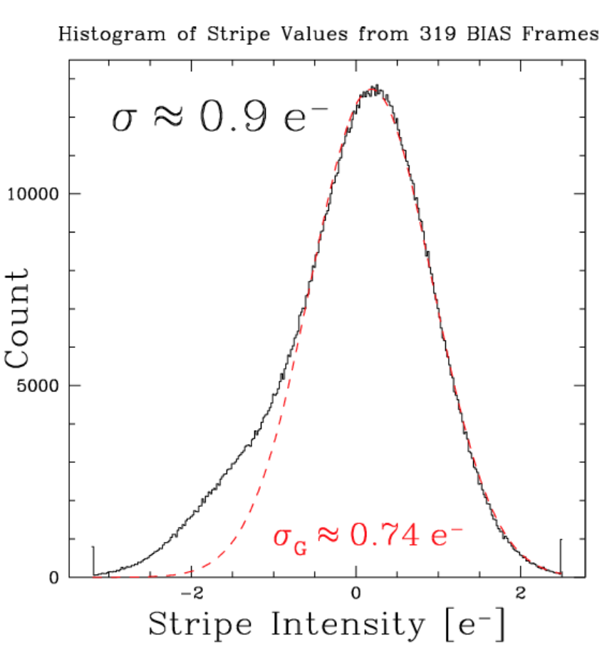
Because of the uniformity of the striping across WFC rows, it is straightforward to characterize and remove this low-level 1/f noise from WFC bias frames. The amplitude distribution is well fit by a Gaussian of σG = 0.74 e¯ with an enhanced negative tail, giving an overall σ = 0.9 e¯, as shown in Figure 4.5 (ACS ISR 2011-05). A more recent study on the bias striping evolution from 2009-2023, ACS ISR 2024-03, shows the striping noise intensity has remained stable since its initial detection post-SM4, and continues to be less than 20% of the WFC read noise. Averaging N bias images reduces the 1/f noise by nearly a factor of N1/2, so the total noise in the post-SM4 WFC superbias reference images is significantly lower than individual frames, as shown in Figure 4.4. See discussion in Section 3.4.1 on bias striping removal in CALACS, as well as documentation for acs_destripe_plus within acstools.
Figure 4.5: Characterization of the Low-level 1/f Noise from WFC Bias Frames
Post-SM4 WFC Signal-dependent Bias Shift
The DSI mode of WFC operation induces a signal-dependent bias shift, the cause of which is closely related to that of the bias gradient described above. The DC level of the DSI mode is sensitive to changes in the CCD output voltage in such a way that the pixel bias level is shifted positively by 0.02%–0.30% (depending on the amplifier) of the signal from the previously integrated pixel. This phenomenon is well characterized for ACS/WFC full frame images and can be analytically removed using a parametric algorithm described in ACS ISR 2012-02. The calacs pipeline now performs this correction, for ACS/WFC post-SM4 full frame and supported 2K subarray images, during the doBlev stage.
WFC Readout Dark
During the readout of every WFC image, dark current continues to accumulate in pixels whose charge has not yet been transferred to the serial register (ACS ISR 2014-02). Since the time for a given pixel to read out depends on its vertical distance from the amplifier, there is a gradient along the columns in accumulated readout dark counts, which adds to the bias gradient. Hot pixels also continue to bleed charge during readout, resulting in hot columns. The superbias reference file removes readout dark current from an image's SCI arrays, accounts for readout dark noise in the ERR arrays, and flags unstable hot columns in the DQ arrays during doBias (ACS ISR 2017-13, ACS ISR 2020-04).
HRC Bias Level Determination
HRC images were read out using only one amplifier. Each image has three overscan regions: a physical pre-scan and overscan of width 19 pixels at columns 1–19 and 1044–1062, and virtual overscan of width 20 pixels at rows 1025–1044. The first 10 columns of the physical pre-scan exhibit bias-settling behavior similar to that described for the WFC quadrants. The bias level is therefore measured in the last six columns of the pre-scan. There is not a significant difference between the bias levels in the pre-scan and imaging regions of the CCD.
4.2.2 Bias Jump
WFC images obtained before SM4 showed intermittent bias variations of a few tenths of a DN during readout. Bias frames occasionally exhibited horizontal bias jumps in one or more quadrants that lasted for several hundreds of rows (Figure 4.6). The probable cause of these jumps was electronic interference from other scientific instruments and/or spacecraft activities. There is no automatic detection of these bias jumps within the calibration pipeline. Bias jumps at the sub-DN level are not important for most science applications, but users should be aware of their possible existence in their calacs image products.
Figure 4.6: Bias Frame with Bias Jump in WFC1 Quadrant B
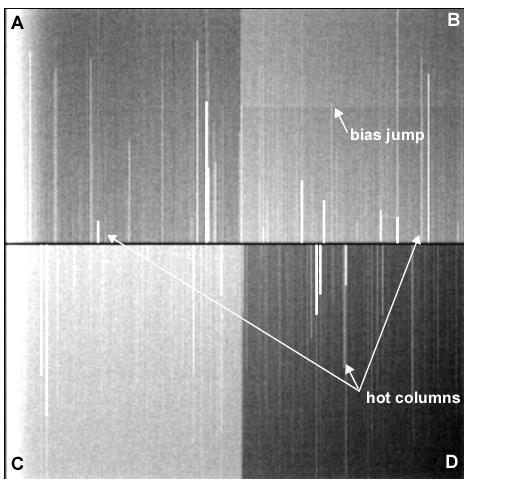
The bias jump is seen in the WFC1 quadrant B only. The vertical stripes in the data are hot columns and are unrelated to bias.
4.2.3 Bias Subarrays for WFC and HRC
Before SM4, the superbias reference frames for science images obtained with WFC and HRC subarray readout modes were simply extracted from the appropriate locations of the full-frame superbias reference images (provided the subarrays did not cross quadrant boundaries). Tests showed that subarray science images that were calibrated with the relevant extracted regions from a full-frame superbias were just as good as those calibrated using superbiases with the same subarray readout patterns. Users were advised not to use subarrays that spanned amplifier quadrants because doing so required the procurement of single amplifier subarray bias images at the expense of the users' observing time.
Unfortunately, this convenient use of full-frame superbiases became unsuitable for post-SM4 subarray science images because the two-dimensional bias gradients imposed by the DSI (see Section 4.2.1) are dependent on the timing patterns used to read out the CCD. The bias gradients seen in the standard 512 × 512 and 1024 × 1024 subarray images are significantly different from the gradients seen in the full-quadrant and full-frame readout modes.
For the post-SM4 Cycles 17–23, subarray bias reference images were obtained based on the number and nature of the science programs that planned to use subarrays during any given cycle:
- For GO programs (with well-defined scheduling windows) the subarray bias reference frames were inserted directly into the GO proposal and linked to the science visits so that they were obtained within two weeks of the science exposures.
- For SNAP programs (with no scheduling windows) subarray superbiases were created at bi-weekly intervals.
- User-defined subarrays are no longer supported.
In May 2016, partway through HST Cycle 23, the ACS flight software was changed to introduce a new set of WFC subarray modes that make obsolete the modes used during post-SM4 Cycles 17–23 (ACS ISR 2017-03). These subarray modes were designed to have the identical readout timing pattern as the WFC full-frame mode, except with readout from only one amplifier (always 2048 columns plus pre-scan) and potentially with fewer rows (512 or 1024 rows; 2048-row subarray also available). On-orbit tests in November 2015 indicated that these revised subarray modes successfully reproduce the full-frame bias gradient structure. Superbias reference files for these subarray modes are extracted from the appropriate locations of the full-frame bias reference files once again. An initial, pedestal-like offset was found in the new, calacs-processed subarray images between amplifiers A and C and amplifiers B and D. The offset was due to an incorrect mapping of the overscan regions in the OSCNTAB reference calibration file for amplifiers B and D. An updated version of the OSCNTAB reference file was released in February 2017 to remove the pedestal-like offset (ACS ISR 2017-06).
The calacs pipeline is designed to perform bias subtraction of both pre-SM4 and post-SM4 WFC subarray images; no special directions for the calibration pipeline are needed. The pipeline initially performs a search for contemporary superbias images with the appropriate subarray dimensions and, if unsuccessful, reverts to the pre-SM4 procedure of extracting the corresponding region from a contemporary full frame superbias.