1.1 Instrument Overview
Wide Field Camera 3 (WFC3) is a fourth-generation imaging instrument installed on the Hubble Space Telescope during Servicing Mission 4 in 2009. It replaced the extraordinarily successful Wide Field Planetary Camera 2 (WFPC2), thereby ensuring and enhancing the imaging capability of HST in the remaining years of its observing lifetime. WFC3 is the only HST instrument developed as a facility instrument by the HST Project.
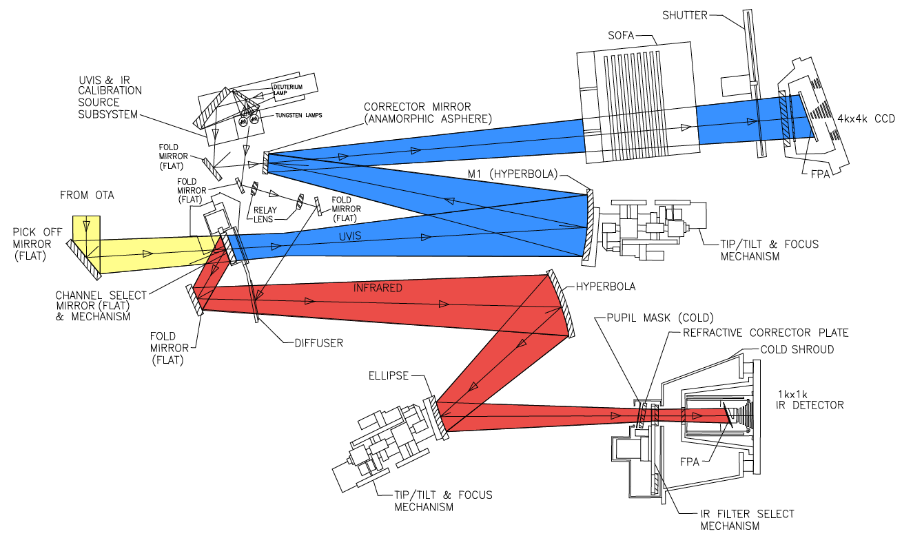
WFC3 occupies WFPC2's spot in HST's radial scientific-instrument bay, where it obtains on-axis direct images. Light entering from the HST Optical Telescope Assembly (OTA) is intercepted by the flat 45 degree WFC3 pick-off mirror (POM) and directed into the instrument. A channel-select mechanism (CSM) inside WFC3 then diverts the light to the IR channel via a fold mirror, or when the CSM is moved out of the beam, the light enters the UVIS channel unimpeded. Because of this design, only a single channel, either UVIS or IR, can be used at any one time. Figure 1.1 shows a schematic diagram of the instrument's optical and mechanical layout. The main characteristics of each channel are summarized in the following sections. For a technical description of the instrument's properties, performance, operations, and calibration, please refer to the WFC3 Instrument Handbook.
For schematic simplicity, the incoming OTA beam and POM have been rotated into the plane of the optical diagram. The actual incoming OTA beam direction is into the page and then reflected by the POM into the instrument (yellow path). The CSM is then either moved out of the beam to allow light to pass into the UVIS channel (blue path), or the CSM is moved into the beam to direct light into the IR channel (red path). Each channel contains mechanical and optical elements which allow for focusing and alignment, as well as anamorphic aspherical correctors to correct for the ~1/2 wave spherical aberration from the HST primary mirror. Filters and grisms are contained in the UVIS selectable optical filter assembly (SOFA) and the IR filter selection mechanism (FSM). The UVIS channel has a mechanical shutter, while the IR channel is shuttered electronically by the detector via a a reset of the entire array. The IR channel's FSM also contains an aluminum blocker ('blank') in one of the filter slots that is in place when the channel is not in use. Light is detected by either the UVIS CCDs or the IR HgCdTe focal-plane array. A separate calibration subsystem with deuterium and tungsten bulbs provides flat-field illumination for both channels.
WFC3 provides HST with high-sensitivity, high-resolution, wide-field survey capability covering a broad wavelength range, from the near-UV at 200 nm to the near-IR at 1700 nm. WFC3 is comprised of two channels, each optimized for a specific wavelength regime:
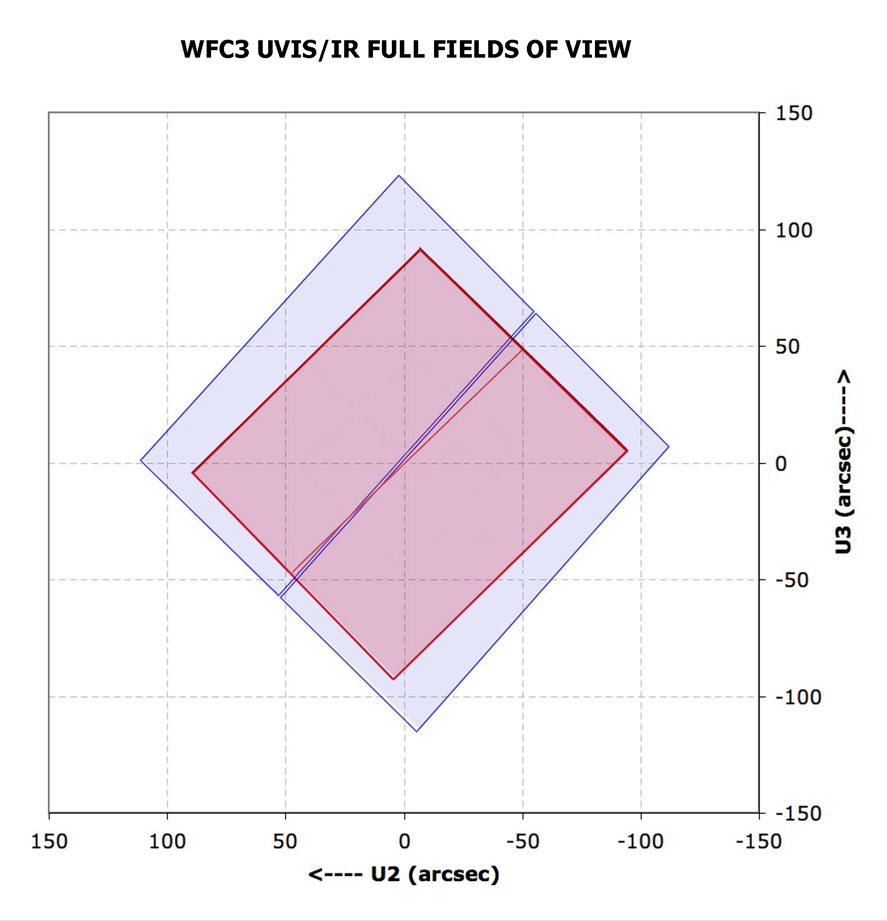
- Ultraviolet-Visible channel (UVIS): sensitive to 200-1000 nm, with a pair of CCDs covering a 162 × 162" total field of view (Figure 1.2), with a plate scale of 0.040"/pixel and a focal ratio of f/31.
- Infrared channel (IR): sensitive to 800-1700 nm, an IR focal plane array covering a 136 × 123" field of view (Figure 1.2), with a plate scale of 0.13"/pixel and a focal ratio of f/11.
WFC3 provides the user with:
- 62 wide-, medium-, and narrow-band filters in the UVIS channel
- 15 wide-, medium-, and narrow-band filters in the IR channel
- 3 grisms: 1 in the UVIS channel and 2 in the IR channel
-
WFC3 Data Handbook
- • Acknowledgments
- • What's New in This Revision
- Preface
- Chapter 1: WFC3 Instruments
- Chapter 2: WFC3 Data Structure
- Chapter 3: WFC3 Data Calibration
- Chapter 4: WFC3 Images: Distortion Correction and AstroDrizzle
- Chapter 5: WFC3 UVIS Sources of Error
- Chapter 6: WFC3 UVIS Charge Transfer Efficiency - CTE
-
Chapter 7: WFC3 IR Sources of Error
- • 7.1 WFC3 IR Error Source Overview
- • 7.2 Gain
- • 7.3 WFC3 IR Bias Correction
- • 7.4 WFC3 Dark Current and Banding
- • 7.5 Blobs
- • 7.6 Detector Nonlinearity Issues
- • 7.7 Count Rate Non-Linearity
- • 7.8 IR Flat Fields
- • 7.9 Pixel Defects and Bad Imaging Regions
- • 7.10 Time-Variable Background
- • 7.11 IR Photometry Errors
- • 7.12 References
- Chapter 8: Persistence in WFC3 IR
- Chapter 9: WFC3 Data Analysis
- Chapter 10: WFC3 Spatial Scan Data

