1.2 The UVIS Channel
The UVIS channel employs a mosaic of two 4096 × 2051 Teledyne e2v (formerly Marconi Applied Technologies Ltd.) CCDs, with ~0.040"/pixel plate scale, covering a nominal 162" × 162" field of view. These CCDs are thinned, back-illuminated devices cooled by thermo-electric cooler (TEC) stacks and housed in sealed, evacuated dewars with fused silica windows, nearly identical to the ones used for ACS. The spectral response of the UVIS CCDs is optimized for imaging from the near-UV at 200 nm to visible wavelengths at 1000 nm. The two CCDs are butted together with a 35-pixel gap between the two chips (~1.4" on the sky). The minimum UVIS exposure time is 0.5 sec. The dynamic range for a single exposure is ultimately limited by the depth of the CCD full well (~70,000 electrons), which determines the total amount of charge that can accumulate in any one pixel during an exposure without saturation.
The UVIS detector operates only in ACCUM mode to produce time-integrated images. Cosmic rays affect all UVIS exposures, therefore observations should be broken into multiple exposures or dither patterns whenever possible, to allow removal of cosmic rays in post-observation data processing.
WFC3 recycles hardware used in WF/PC-1 to house the complement of filters for the UVIS channel. The Selectable Optical Filter Assembly (SOFA) contains a stack of 12 wheels housing 48 physical elements covering the UV/Visible range: 42 full-frame filters, 5 quad filters (2 × 2 mosaics providing 4 different bandpasses), and 1 grism, giving a total of 63 spectral elements. Each wheel has an open slot such that when an observation is taking place, the appropriate wheel is rotated to place the desired filter in the beam, while the other wheels place the open slot in the light path.
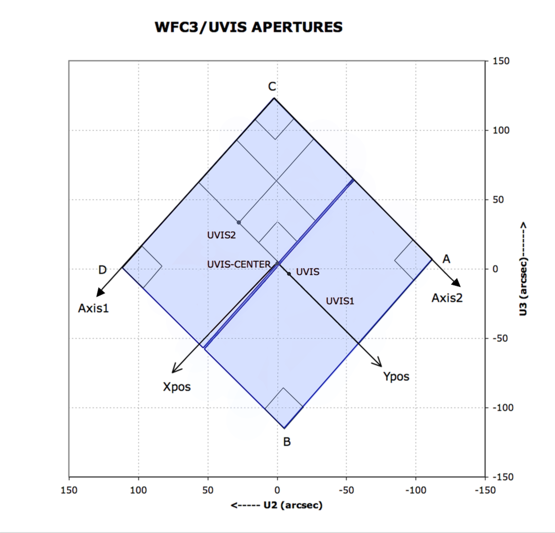
Figure 1.3 shows a schematic of the UVIS channel aperture projected onto the sky with respect to the U2/U3 reference frame. (For definitions of the coordinate systems in the figure, please refer to Section 7.4.3 of the WFC3 Instrument Handbook). The WFC3 optics cause the nominally square field of view of the UVIS detector to be projected onto the sky as a skewed rhombus, 162" on a side, with an angle of 86.1 degrees between the sides. This distortion affects both the photometric accuracy and astrometric precision of the UVIS images. For a thorough discussion of WFC3’s geometric distortion, we refer the reader to Chapter 4.
Figure 1.3: This UVIS Aperture Diagram illustrates the regions imaged by the UVIS detector (represented by blue fill), the fiducial points of the full-detector apertures (UVIS, UVIS1, UVIS2, and UVIS-CENTER), and the outlines of the 2K × 2K, 1K × 1K, and 512 × 512 subarray apertures. Also indicated are the positions of the four readout amplifiers (A, B, C, and D). The POSition TARGet (POSTARG) coordinate system for the UVIS-CENTER aperture, with its origin at that aperture's fiducial point, is illustrated. Although the POSTARG coordinate systems for the other apertures are not illustrated, they are oriented the same, but have origins at each aperture's fiducial point. (U2 = –V2 and U3 = –V3).
-
WFC3 Data Handbook
- • Acknowledgments
- • What's New in This Revision
- Preface
- Chapter 1: WFC3 Instruments
- Chapter 2: WFC3 Data Structure
- Chapter 3: WFC3 Data Calibration
- Chapter 4: WFC3 Images: Distortion Correction and AstroDrizzle
- Chapter 5: WFC3 UVIS Sources of Error
- Chapter 6: WFC3 UVIS Charge Transfer Efficiency - CTE
-
Chapter 7: WFC3 IR Sources of Error
- • 7.1 WFC3 IR Error Source Overview
- • 7.2 Gain
- • 7.3 WFC3 IR Bias Correction
- • 7.4 WFC3 Dark Current and Banding
- • 7.5 Blobs
- • 7.6 Detector Nonlinearity Issues
- • 7.7 Count Rate Non-Linearity
- • 7.8 IR Flat Fields
- • 7.9 Pixel Defects and Bad Imaging Regions
- • 7.10 Time-Variable Background
- • 7.11 IR Photometry Errors
- • 7.12 References
- Chapter 8: Persistence in WFC3 IR
- Chapter 9: WFC3 Data Analysis
- Chapter 10: WFC3 Spatial Scan Data
