7.6 Detector Nonlinearity Issues
7.6.1 Nonlinearity Calibrations
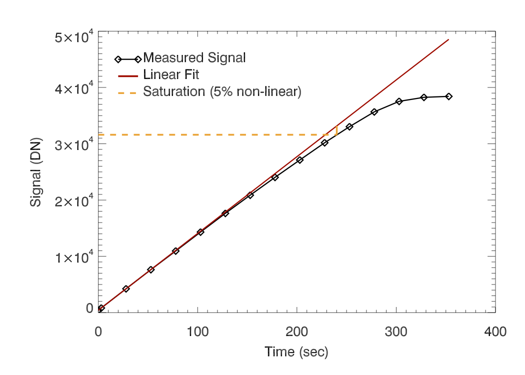
HgCdTe detectors, such as that in the WFC3/IR channel, are inherently non-linear in their response to incident photons. Figure 7.6 shows the measured signal up the ramp for a single pixel during a flat-field ramp. The black diamonds show that the measured signal is clearly non-linear as the signal increases. The red line is a linear fit to reads at low signal levels, extended out to the end of the ramp. The difference between these two lines (normalized by the measured signal values) represents the amount of non-linearity in the measured signal. By measuring this difference for each pixel using a set of flat-field ramps, the non-linearity behavior of each pixel is characterized, and a correction produced. This correction takes the form of a 3rd order polynomial, as seen in the equation below, that relates the measured and idealized signal and is applied by calwf3 in the NLINCORR step of the processing. Further details can be found in WFC3 ISR 2008-39.
The non-linearity correction in calwf3 currently uses quadrant-averaged polynomials derived from ground testing data. Only small improvements in the nonlinearity calibration are anticipated from using on-orbit flat fields, and noticeable differences have been measured between nonlinearity corrections applied to flat fields compared to stars. For those reasons, the methods and results described in WFC3 ISR 2014-17 have not been implemented.
7.6.2 Non-Zero Zeroth Read Correction for Bright Sources
As described in Section 7.3, the first non-destructive readout after the detector reset provides the reference bias level for each pixel in a WFC3/IR science image. This image is referred to as the ‘zeroth readout’ or ‘zeroth read’. Due to the timing patterns in use, this read is collected at a finite time after the detector is reset. Because the IR channel has no shutter, when a bright source is present in the field, a non-negligible amount of charge may accumulate on the detector between the time of the detector reset and the zeroth read. This implies that after the subtraction of the zeroth read from all subsequent reads in a ramp, the pixels at the location of the bright source will be under-reporting the amount of signal they were subjected to during the ramp. While this has no effect on the calwf3 calculation of the signal rate, it can lead to errors in the non-linearity correction step, since this correction is based on the absolute signal level.
Prior to March 2011, in order to correct for this situation, the ZSIGCORR step in calwf3 (very similar to that in the calnica software for NICMOS) computes an estimate of the number of counts for each pixel in the zeroth readout of a MULTIACCUM ramp, based on the count rate measured between the first two reads. After March 2011, the bias is read from a linearity reference file and subtracted from the zeroth read of the file being processed. (see Section 3.3.2 for details). This information is then used in the non-linearity correction (NLINCORR) step to estimate the absolute signal in each pixel and apply the appropriate linearity correction and saturation checks for that signal level.
-
WFC3 Data Handbook
- • Acknowledgments
- • What's New in This Revision
- Preface
- Chapter 1: WFC3 Instruments
- Chapter 2: WFC3 Data Structure
- Chapter 3: WFC3 Data Calibration
- Chapter 4: WFC3 Images: Distortion Correction and AstroDrizzle
- Chapter 5: WFC3 UVIS Sources of Error
- Chapter 6: WFC3 UVIS Charge Transfer Efficiency - CTE
-
Chapter 7: WFC3 IR Sources of Error
- • 7.1 WFC3 IR Error Source Overview
- • 7.2 Gain
- • 7.3 WFC3 IR Bias Correction
- • 7.4 WFC3 Dark Current and Banding
- • 7.5 Blobs
- • 7.6 Detector Nonlinearity Issues
- • 7.7 Count Rate Non-Linearity
- • 7.8 IR Flat Fields
- • 7.9 Pixel Defects and Bad Imaging Regions
- • 7.10 Time-Variable Background
- • 7.11 IR Photometry Errors
- • 7.12 References
- Chapter 8: Persistence in WFC3 IR
- Chapter 9: WFC3 Data Analysis
- Chapter 10: WFC3 Spatial Scan Data
