1.3 The IR Channel
The IR detector employs a 1024 × 1024 Teledyne (formerly Rockwell Scientific) low noise, high quantum efficiency (QE) HgCdTe detector array with ~0.13" pixels, covering a nominal 136 × 123" field of view. Only the central 1014 × 1014 pixels are useful for imaging. The outer rind, 5 pixels in width, contains light-insensitive pixels that are used as reference. The HgCdTe array is actively cooled by a six-stage TEC that maintains the detector at a nominal operating temperature of 145 K. The spectral response of the IR detector is optimized for imaging at near-IR wavelengths from approximately 800 to 1700 nm.
IR detectors allow accumulated signal to be read out non-destructively multiple times without affecting other pixels (a mode referred to as MULTIACCUM). This capability can be exploited to significantly reduce the effective read-out noise, enable recovery of sources that saturate during the integration time, and enable recovery of pixels affected by cosmic rays (CR), since CRs may be recognized and removed between adjacent reads.
The WFC3-IR detector is immune to the charge bleeding exhibited by CCDs at high signal levels; however, saturation can still be a problem because pixels subject to the highest signal levels show higher dark current rates ("image persistence") in subsequent exposures (see Chapter 8). IR detectors do not show long-term on-orbit charge transfer efficiency (CTE) degradation, because they do not employ the charge-transfer mechanism used in CCDs. However, they are intrinsically non-linear, although at low and intermediate count levels, the departure from linearity is quite modest and can be well calibrated.
The IR channel has a single filter wheel housing 17 spectral elements covering the near-IR wavelengths: 15 filters and 2 grisms. An 18th slot contains an opaque aluminum blocker (called a Blank). For IR observations, the requested element is simply rotated into the light beam. The IR channel operates only in MULTIACCUM mode. The WFC3 IR channel does not have a mechanical shutter, thus when the channel is not in use, the Blank is moved into the beam to block light from entering the detector, and the detector itself is continuously reset at the fastest possible rate (i.e. read out as fast as possible) for the full frame (about 2.93 seconds.)
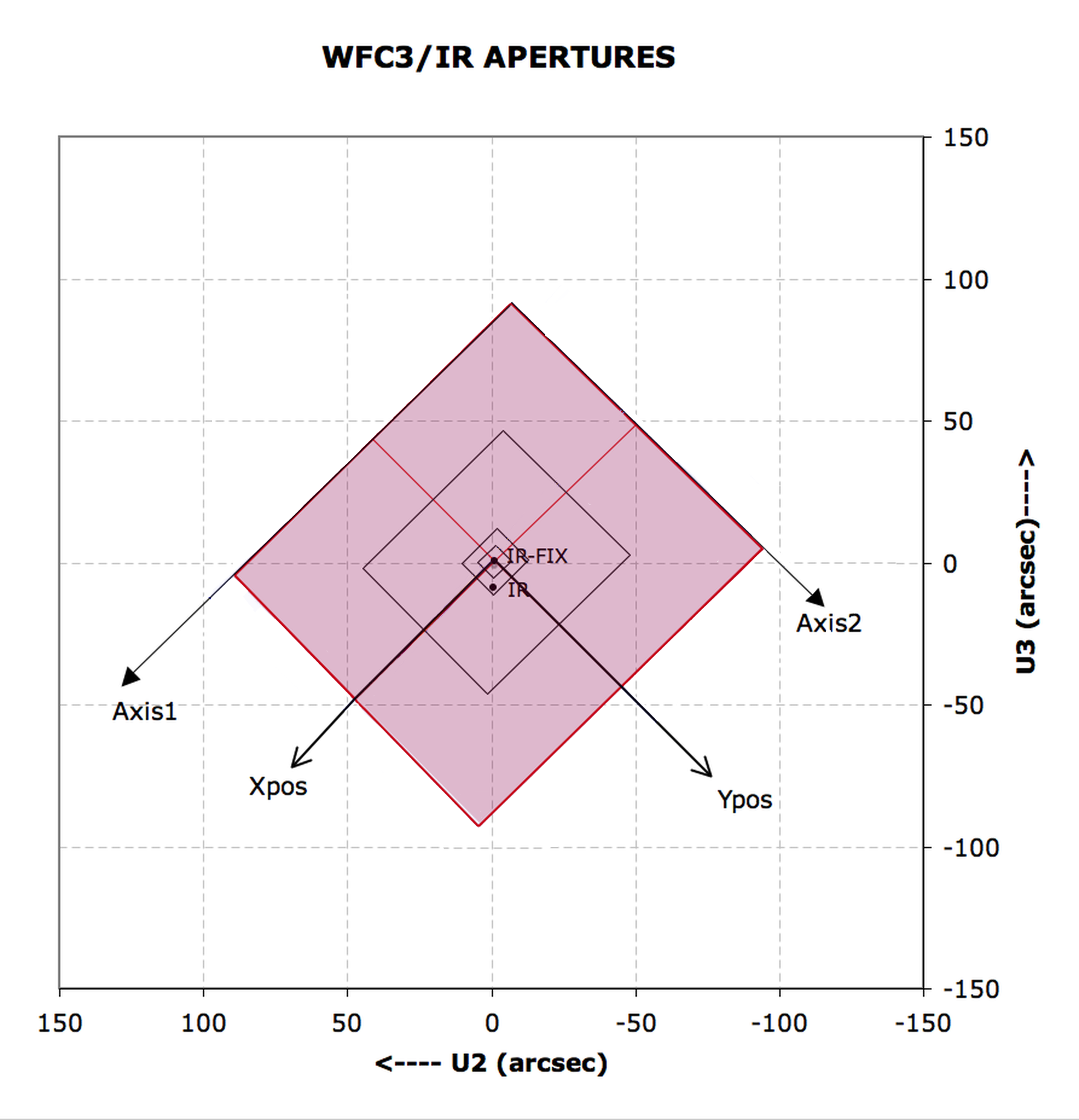
Figure 1.4 shows a schematic of the IR channel aperture projected onto the sky with respect to the U2/U3 reference frame. (For definitions of the coordinate systems in the figure, please refer to Section 6.4.3 of the WFC3 Instrument Handbook) The IR focal plane is tilted 22 degrees with respect to the incoming beam, thus the field of view as projected onto the sky is rectangular, with an aspect ratio of ~0.90. This distortion affects both the photometric accuracy and astrometric precision of the IR images. For a thorough discussion of WFC3 geometric distortion, we refer the reader to Chapter 4.
-
WFC3 Data Handbook
- • Acknowledgments
- • What's New in This Revision
- Preface
- Chapter 1: WFC3 Instruments
- Chapter 2: WFC3 Data Structure
- Chapter 3: WFC3 Data Calibration
- Chapter 4: WFC3 Images: Distortion Correction and AstroDrizzle
- Chapter 5: WFC3 UVIS Sources of Error
- Chapter 6: WFC3 UVIS Charge Transfer Efficiency - CTE
-
Chapter 7: WFC3 IR Sources of Error
- • 7.1 WFC3 IR Error Source Overview
- • 7.2 Gain
- • 7.3 WFC3 IR Bias Correction
- • 7.4 WFC3 Dark Current and Banding
- • 7.5 Blobs
- • 7.6 Detector Nonlinearity Issues
- • 7.7 Count Rate Non-Linearity
- • 7.8 IR Flat Fields
- • 7.9 Pixel Defects and Bad Imaging Regions
- • 7.10 Time-Variable Background
- • 7.11 IR Photometry Errors
- • 7.12 References
- Chapter 8: Persistence in WFC3 IR
- Chapter 9: WFC3 Data Analysis
- Chapter 10: WFC3 Spatial Scan Data
