5.6 Generic Detector and Camera Properties
5.6.1 Full Well Depth
Conceptually, full well depths can be derived by analyzing images of a rich starfield taken at two significantly different exposure times, identifying bright but still unsaturated stars in the short exposure image, calculating which stars will saturate in the longer exposure and then simply recording the peak value reached for each star in electrons (using a gain that samples the full well depth, of course). In practice, it is also necessary to correct for a ~10% "piling up" effect of higher values being reached at significant levels of over-saturation relative to the value at which saturation and bleeding to neighboring pixels in the column begins (see WFC3 ISR 2010-10).
Since the full well depth varies over the CCDs, it is desirable to observe a rich star field with a gain that samples the full well depth (e.g. the default WFC3 UVIS gain), and for which a large number of stars saturate. Calibration and GO programs have serendipitously supplied the requisite data of rich fields observed at two different exposure times.
There is a real and significant large-scale variation of the full well depth on the UVIS CCDs. The variation over the UVIS CCDs is from about 63,000 e- to 72,000 e- with a typical value of about 68,000 e-. There is a significant offset between the two CCDs, as visible in Figure 5 of WFC3 ISR 2010-10.
Prior to version 3.7.1, the calwf3 calibration pipeline used a single scalar threshold based on the average of these values (SATURATE, in the CCDTAB file) for full well to flag saturated pixels in the science image data quality file. Installed in December 2023, calwf3 version 3.7.1 adopted a new method of UVIS full well saturation flagging that uses a two-dimensional array of pixel threshold values instead of a single scalar threshold applied to the entire image. This is now a deliverable saturation map reference file (SATUFILE) in CRDS (see Section 3.2 for where it is implemented in the pipeline. The first delivery of the SATUFILE still effectively applies the same scalar threshold (WFC3 ISR 2023-08). However, the change lays the foundation for a future delivery of a spatially-dependent saturation map to account for the variation in full well depth across the detectors.
5.6.2 Linearity at Low to Moderate Intensity
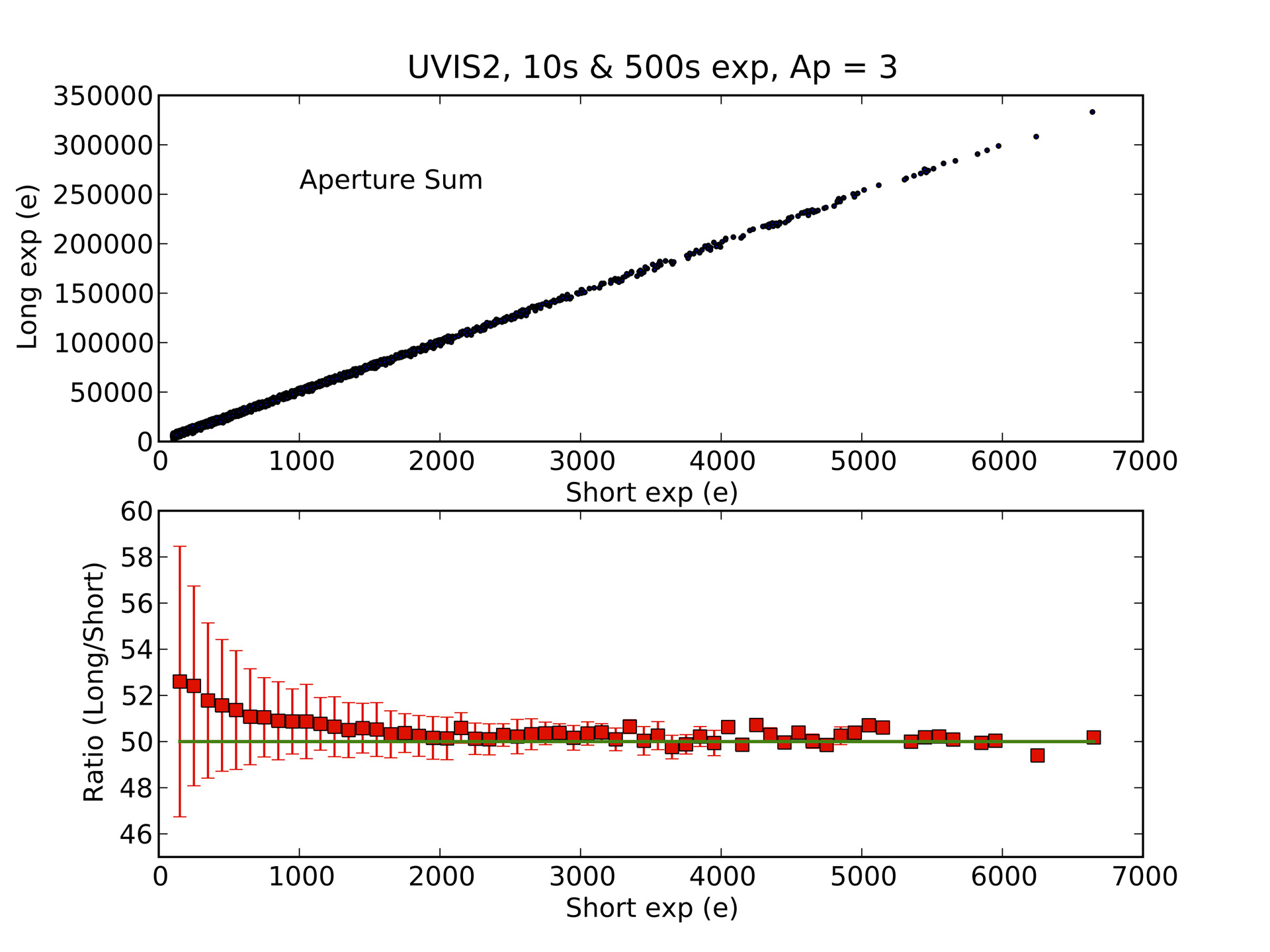
Linearity at low and moderate exposure levels was measured by comparing back-to-back exposures of NGC 1850 made in October 2009. Figure 5.14 shows the response of UVIS2, where aperture sums for stars with flux greater than about 2,000 e- in a short exposure (central pixel greater than about 350 e-) show apparently perfect linear response when compared to the counts in the same aperture in an exposure 50 times as long. However, below a level of 2,000 e- the ratio of long to short exposure counts deviates from a linear response. At a total aperture flux of about 200 e- in the short exposure, the total flux values are ~ 5% lower than expected based on scaling from the corresponding long exposure. This is due to the nature of CTE loss which has a greater effect on fainter sources.
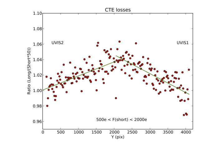
Figure 5.15 shows data from both UVIS CCDs for stars with short exposure aperture sums of 500 to 2000 e-. Stars near the readout amplifiers (y_pix = 0,4095) behave as expected i.e. the short exposure sums scaled by the difference in exposure time are equivalent to the long exposure but losses grow with distance from the amplifiers. This effect is consistent with losses induced by finite charge transfer efficiency in successive parallel shifts in clocking the charge packets off the CCDs.
The WFC3 team monitors the extent to which CTE losses influence faint object photometry. CTE degradation in flight has increasingly affected the measurement of unsaturated images over the years, requiring increasingly greater flux corrections with larger uncertainties. The most recent CTE loss results are summarized in Chapter 6.
Figure 5.14: Loss of linearity at low and moderate intensity due to finite Charge Transfer Efficiency.
The upper panel shows the counts in r = 3 pixel apertures for several thousand stars in back-to-back 500s and 10s exposures (from 2009) plotted against each other. To better illustrate small differences, the lower panel shows the same data after binning and plotting as the ratio of long to short exposure time; 50.0 denotes perfect linearity.
Figure 5.15: UVIS1 and UVIS2 CTE Losses For a Short Exposure
Ratio of fluxes in short and long exposures as a function of Y position. Plot is based on data from the previous figure for UVIS2, plus similar data for UVIS1 plotted against y-position in the concatenated detector space (images from 2009). Y-values near 2050 correspond to the maximum distance from the readout amplifiers, and hence the most parallel shifts inducing CTE losses.
5.6.3 Linearity Beyond Saturation
The response of the WFC3 UVIS CCDs is linear well beyond the point of saturation. WFC3 ISR 2010-10 shows the well-behaved response of WFC3: electrons are clearly conserved after saturation -- in some locations with the need for a minor calibration, as provided in the ISR, while in other regions no correction is needed. This result is similar to those of the STIS CCD (Gilliland et al. 1999), the WFPC2 camera (Gilliland, 1994), and the ACS (ACS ISR 2004-01). It is possible to easily perform photometry on point sources that remain isolated simply by summing over all of the pixels into which the charge has bled.
To characterize the accuracy of point source photometry for sources in which one or more pixels have exceeded the physical full well depth, we used a dataset consisting of alternating short and long exposures of a moderate-to-rich star field, resulting in both unsaturated and saturated images for many stars. Counts were summed over an area designed to include all pixels in the core of the stellar image and all pixels that were bled into in the long exposures.
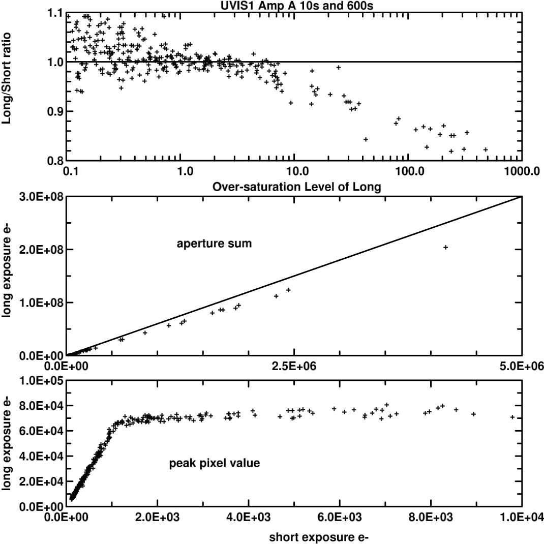
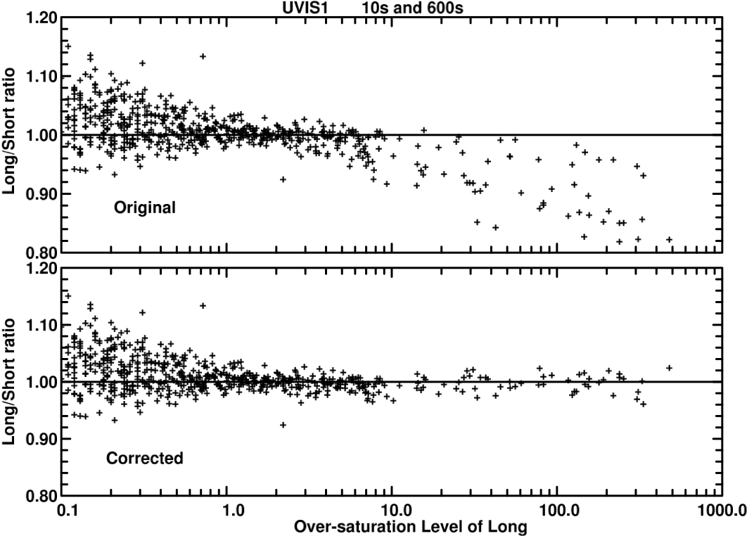
Departures from linearity were greater for UVIS1 than for UVIS2. Results for Amp A and UVIS1 are summarized in Figure 5.16 and Figure 5.17. Over a range of nearly 7 magnitudes beyond saturation, photometry remains linear to ~ 1% after a simple correction (WFC3 ISR 2010-10). For Amp C on UVIS2, the response is sufficiently linear beyond saturation that no correction is required. These results were obtained when CTE was near pre-flight levels in October 2009. See Section 5.6.2 for the level of CTE loss that was already measurable at that time. CTE degradation in flight has increasingly affected the measurement of unsaturated images over the years, requiring increasingly greater flux corrections with larger uncertainties.
While these results are based on the use of *_flt.fits images, the flux conservation ensured by AstroDrizzle leads to equally good results for linearity beyond saturation when comparing long and short *_drz.fits images.
Figure 5.16: Linearity Analysis for Amp A
Linearity beyond saturation for Amp A on UVIS1 in data from 2009. The upper panel shows the ratio of counts in the long exposure divided by the counts in the short exposure multiplied by the relative exposure time; a value of unity indicates perfect linearity. The x-axis shows the multiplicative degree by which a star is over-saturated in the long exposure. The middle panel shows the long exposure aperture sums versus short exposure aperture sums. The lower panel shows the peak data value in the long exposure relative to the short exposure value. The response is linear up to 68,000 e- (y-axis) where the long exposure encounters saturation. Amp A data show significant deviations from a linear response for over-saturations near and beyond a factor of 10.
Figure 5.17: Long vs. Short Exposure Ratios of Linearity
Top panel shows the count rate ratio between long and short exposures for both amplifier quadrants of UVIS1 (Amps A and B) vs. the over-saturation level in the long exposure in data from 2009. Bottom panel shows the same data but after applying the corrections as described in WFC3 ISR 2010-10. At high levels of saturation, the Long to Short count ratios are restored to unity and the scatter is signficantly reduced.
5.6.4 Shutter Stability
The WFC3-UVIS shutter is a circular, rotating blade divided into two open and two closed quadrants (See Section 2.3.3 of the WFC3 Instrument Handbook for details). Operationally, the shutter mechanism has two distinct modes, based on the commanded exposure time. At the shortest commanded exposure time of 0.5 seconds, the shutter's motion is continuous during the exposure, rotating from the closed position through the open position and on to the next closed position. For commanded exposure times of 0.7 seconds and longer, the shutter rotates into the open position, stops and waits for an appropriate amount of time, and then rotates to the closed position.
Using series of short exposures during SMOV, the “shutter shading,” i.e. position-dependent exposure time, shutter blade dependence (A blade or B blade), shutter timing repeatability, and shutter timing accuracy were all assessed (see WFC3 ISR 2009-25 and WFC3 ISR 2015-12). Shutter shading does not exceed ~0.2% across the detector, so no correction for shutter shading is performed in calwf3.
Stellar PSFs in short exposures taken with shutter B show slightly larger FWHM and lower sharpness compared to those taken with shutter A, especially in the shortest, 0.5-sec, exposures (WFC3 ISR 2014-09). In order to facilitate the science where short exposures are necessary and a good and stable PSF is crucial, use the available-mode option in in APT to select the shutter blade A. No other systematic difference in shutter behavior (exposure time, repeatability, etc.) has been found when comparing the A and B blades of the shutter.
The stability of shutter timing is a bit more problematic. Very early on-orbit results were based on eleven white dwarf standard star images; for exposure times of 0.5, 0.7, 0.8, and 1.0 seconds, the rms variation was measured at 1.9%, 1.6%, and 1.5%, and 1.0%, respectively (WFC3 ISR 2009-25). These results for direct images must include photometric errors from variations in pointing, PSF variations, and flat field errors in addition to shutter timing variation thus the results are upper bounds to the variation in shutter timing alone.
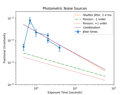
In a more recent study, a spectrophotometric standard star is observed using the G280 grism in order to disperse its light across hundreds of pixels, allowing for high photometric precision in very short exposures to more precisely measure the shutter timing jitter (WFC3 ISR 2023-04). The actual exposure time was found to vary by 2.43 +/- 0.32 milliseconds for exposure times of 1.0, 2.0, and 4.0 seconds, which is nearly four times better than the system requirement and a much smaller rms variation measured in prior analyses. The results also show that the repeatability for 0.5 second exposures is ten times smaller than in longer exposures, which is most likely due to the shutter mechanism not stopping during its open state. Conversely, the timing jitter in 0.7 second exposures is approximately twice that measured in longer exposures, though still within the system requirements. The 0.7 second exposures are most likely affected by the vibration of the shutter system, leading to the somewhat higher variations in the shutter timing.
In short exposures, the shutter jitter dominates Poisson noise as shown in Figure 5.18. Observers should consider avoiding 0.7 second exposures due to its greater shutter timing variation and use the 0.5 or 1.0 second instead when possible. For precision photometry with short exposures, the shutter jitter error should be included in the noise model (WFC3 ISR 2023-04).
Photometric measurements indicate that for commanded exposure times of 0.5 s and 0.7 s, the shutter actually is open for 0.48 s and 0.695 s, respectively (cf. citations earlier in this subsection). The EXPTIME header keyword value in the science image headers reflects these actual (as opposed to commanded) exposure times.
5.6.5 Fringing
At wavelengths longer than about 650 nm, silicon becomes transparent enough that multiple internal reflections in the UVIS detector can create patterns of constructive and destructive interference, or fringing. Fringing produces wood-grain type patterns in images as a result of narrow-band illumination at long wavelengths.
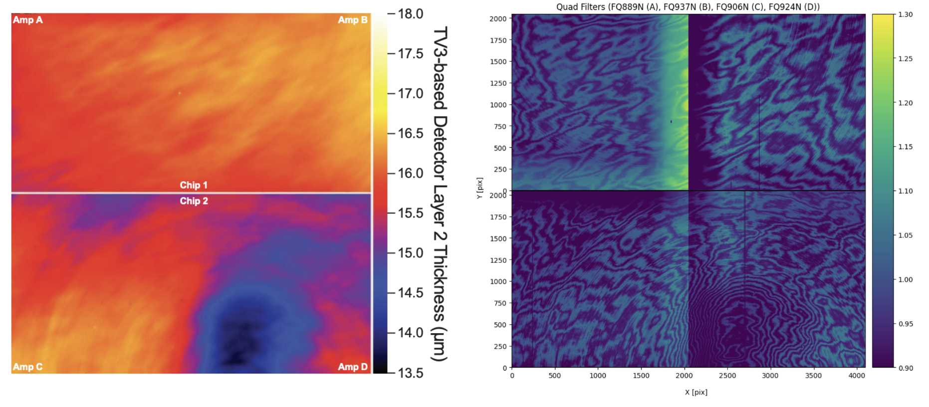
The amplitude and phase of the fringes is a strong function of the silicon detector layer thickness (Figure 5.19) and the spectral energy distribution of the illumination. Detector layer thickness maps are used to model/predict fringing behavior, whose shape generally follows variations in thickness (see Figure 5.19). Fringe amplitude i.e. the contrast between constructive and destructive interference is greatest a) at the longest wavelength (high transparency allows for more internal reflections) and b) for the narrowest spectral energy distributions (SEDs). For broad SEDs, interference is averaged over phase, so that the amplitude of the fringing is reduced. Thus fringing is significant for UVIS imaging data only if red narrow-band filters (e.g. Figure 5.20) are used or sources with red line emission are observed.
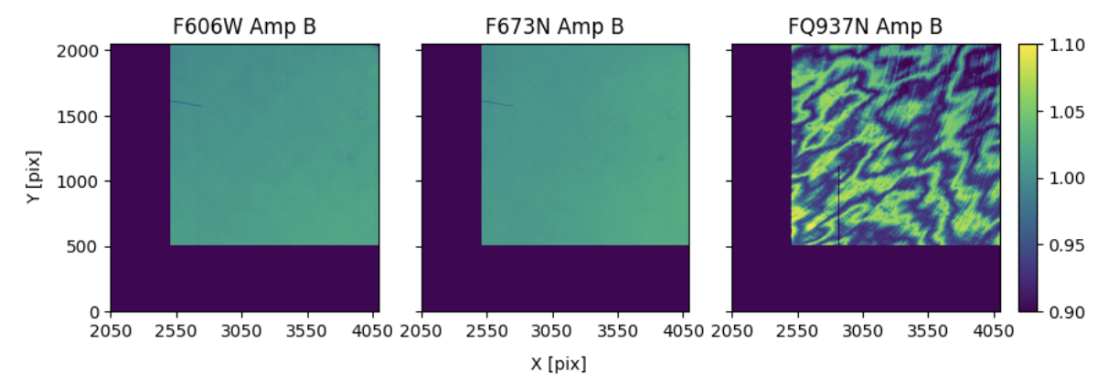
Figure 5.20: Fringing
Quadrant B of three flat fields: the broadband F606W control (left), one narrowband unaffected by fringing (middle), and one affected by fringing (right). Dark blue region of the FQ937N flat is masked to avoid areas impacted by the quad filter edge effects; the same region of F606W and F673N is masked for consistency.
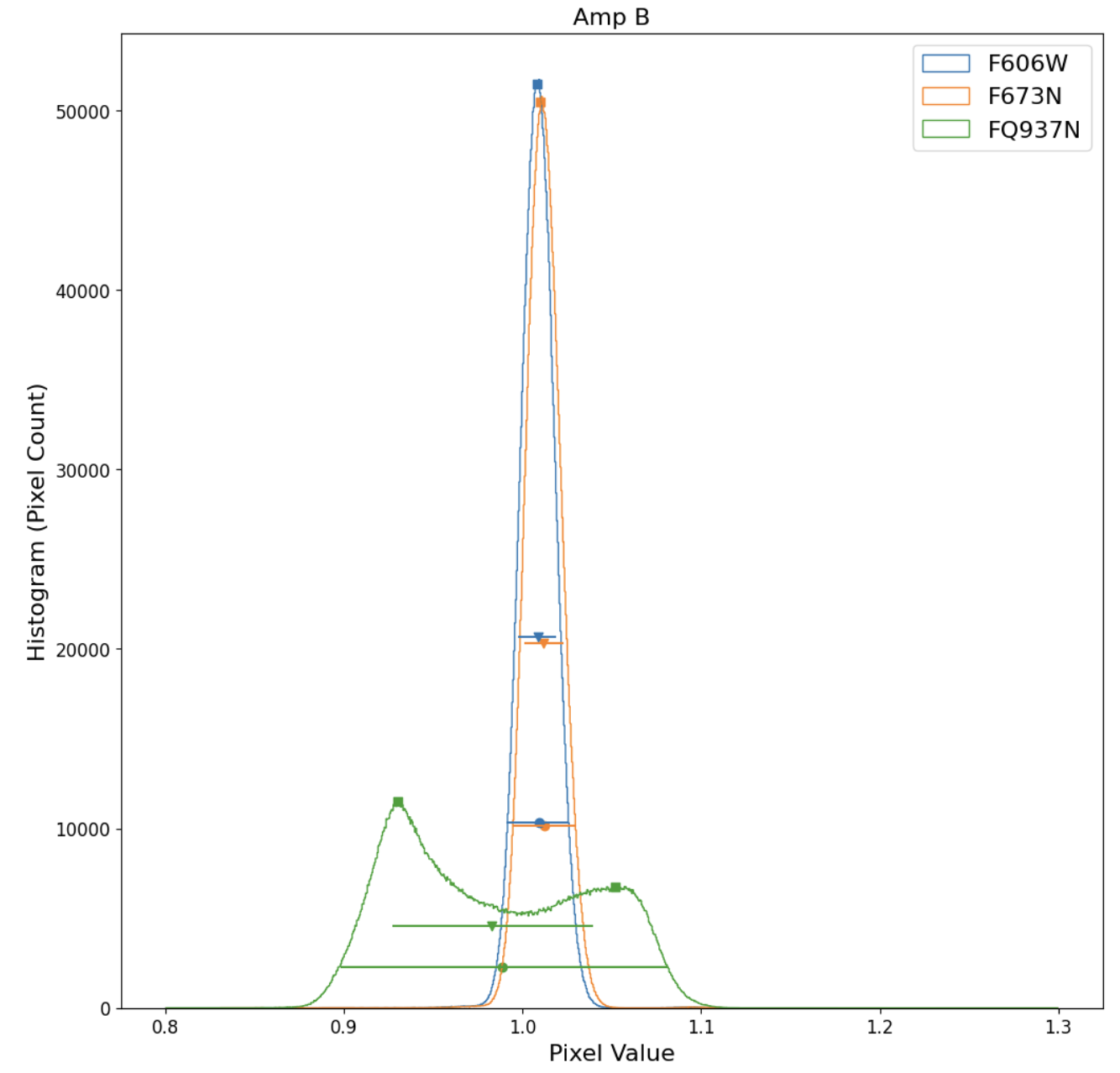
Flat fields from ground tests (WFC3 ISR 2008-46) have been used to estimate the magnitude of fringing effects, for a continuum light source, in the narrow-band red filters (see Table 5.3 and WFC3 ISR 2010-04). Each column lists a different metric of fringe amplitude for filters in which fringing effects could be detected in the flat-field data along with a control filter (F606W) without fringing. These metrics can best be understood by examining the histograms (Figure 5.21) of the flat fields shown in Figure 5.20.
Table 5.3: Metrics of fringe amplitude based on ground flat fields
Filter | Distance Between Histogram Peaks percent | Manual Peak-to Trough percent | Quadrant | RMS Deviation percent | Full Width At 20% Maximum percent |
|---|---|---|---|---|---|
F606W | A | 0.9 | 2.9 | ||
F606W | B | 1.0 | 3.0 | ||
F606W | C | 1.2 | 3.3 | ||
F606W | D | 1.2 | 3.3 | ||
F656N | 2.2 +/-1.2 | A | 1.4 | 4.9 | |
F656N | 1.7 +/- 1.1 | B | 1.3 | 4.5 | |
F656N | 1.7 +/- 1.2 | C | 1.6 | 5.1 | |
F656N | 3.2 +/- 1.3 | D | 1.5 | 5.1 | |
F658N | A | 1.3 | 4.4 | ||
F658N | B | 1.2 | 3.9 | ||
F658N | C | 1.4 | 4.4 | ||
F658N | 0.9 +/- 1.1 | D | 1.3 | 3.7 | |
F673N | A | 0.9 | 3.1 | ||
F673N | B | 1.0 | 3.2 | ||
F673N | C | 1.3 | 3.6 | ||
F673N | 0.5 +/- 1.1 | D | 1.4 | 4.2 | |
F953N | 17.8 | 19.8 +/- 1.7 | A | 7.6 | 23.7 |
F953N | 17.3 | 20.8 +/- 1.8 | B | 7.8 | 24.0 |
F953N | 14.9 | 17.8 +/- 1.7 | C | 7.1 | 23.5 |
F953N | 15.0 | 11.5 +/- 1.6 | D | 6.7 | 22.9 |
FQ672N | 4.6 +/- 1.3 | D | 2.0 | 7.0 | |
FQ674N | 2.4 +/- 1.3 | B | 2.1 | 7.4 | |
FQ727N | 2.3 +/- 1.1 | D | 1.6 | 5.3 | |
FQ750N | 1.2 +/- 1.1 | B | 1.3 | 4.5 | |
FQ889N | 7.8 | 10.0 +/- 1.3 | A | 3.8 | 13.5 |
FQ937N | 12.5 | 12.2 +/- 1.4 | B | 5.4 | 18.2 |
FQ906N | 6.9 | 10.1 +/- 1.4 | C | 4.4 | 16.5 |
FQ924N | 9.4 | 14.2 +/- 1.4 | D | 5.0 | 18.4 |
Values are given in units of percentage of the normalized flat-field signal level. Each metric is described in the text and graphically represented in Figure 5.20.
The fifth data column in the table is simply the root mean square deviation from the mean of the sample and is indicated by triangles with horizontal error bars in the histograms. Filters/quadrants with rms deviations greater than corresponding values for the control filter (F606W) may be influenced by fringing. The last column is full width at 20% maximum, rather than full width at 50% maximum because this metric is more effective for bimodal pixel brightness distributions in filters with strong fringing, such as FQ937N (pictured). The second data column gives the separation between histogram peaks, which can be detected in flat-field data for only the five reddest of the twelve filters affected by fringing. Squares in Figure 5.21 mark the histogram peaks. Adjacent fringes were also manually sampled, and the results reported in the second data column.
-
WFC3 Data Handbook
- • Acknowledgments
- • What's New in This Revision
- Preface
- Chapter 1: WFC3 Instruments
- Chapter 2: WFC3 Data Structure
- Chapter 3: WFC3 Data Calibration
- Chapter 4: WFC3 Images: Distortion Correction and AstroDrizzle
- Chapter 5: WFC3 UVIS Sources of Error
- Chapter 6: WFC3 UVIS Charge Transfer Efficiency - CTE
-
Chapter 7: WFC3 IR Sources of Error
- • 7.1 WFC3 IR Error Source Overview
- • 7.2 Gain
- • 7.3 WFC3 IR Bias Correction
- • 7.4 WFC3 Dark Current and Banding
- • 7.5 Blobs
- • 7.6 Detector Nonlinearity Issues
- • 7.7 Count Rate Non-Linearity
- • 7.8 IR Flat Fields
- • 7.9 Pixel Defects and Bad Imaging Regions
- • 7.10 Time-Variable Background
- • 7.11 IR Photometry Errors
- • 7.12 References
- Chapter 8: Persistence in WFC3 IR
- Chapter 9: WFC3 Data Analysis
- Chapter 10: WFC3 Spatial Scan Data
