7.4 IR Field Geometry
7.4.1 Field of View and Pixel Size
The inner 1014 × 1014 pixels of the IR detector are exposed to incoming light. There are no gaps in the field (such as the gap between the two CCDs in the UVIS channel), or mechanical occultations (such as the coronagraphic spots in NICMOS camera 2).
The IR focal plane is tilted by 24° with respect to the incoming beam. Thus the field of view as projected onto the sky is rectangular, with an aspect ratio of ~0.90. The pixels projected onto the sky are also rectangular, covering approximately 0.135 × 0.121 arcsec, with the shape varying slightly across the field. The field of view on the sky is 136 × 123 arcsec, or 4.65 arcmin2.
7.4.2 Geometric Distortion
In addition to the rectangular field shape described above, the optical design of the IR channel also produces appreciable geometric distortion. Geometric distortions in both channels are discussed in more detail in Appendix B.
Distortion must be taken into account when exposures are flat-fielded, photometrically calibrated, used for astrometric measurements, or combined with other dithered exposures. The AstroDrizzle software appropriately carries out those operations; a combination of software packages in DrizzlePac can be used to optimize the combination of dithered exposures. (See the DrizzlePac documentation.)
7.4.3 Coordinate Systems
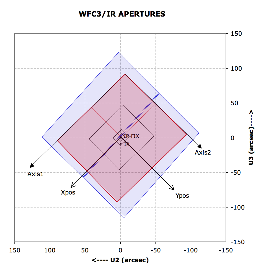
Like the CCD, the IR channel requires multiple coordinate reference frames, each relevant for a specific goal. Readers may also wish to refer to Section 6.4.3, which describes the coordinate systems for the UVIS channel. The coordinate systems used for the IR channel are illustrated in Figure 7.1 and are the following:
- Data image-based system (Axis1, Axis2; units of pixels)
- Proposal POS TARG system (X pos, Ypos; units of arcsec)
- HST-based system (V2, V3 or U2, U3; units of arcsec)
Figure 7.1: Diagram of IR apertures, illustrating the fiducial points of the full-detector apertures (IR and IR-FIX), and the outlines of the concentric subarray apertures (512 × 512, 256 × 256, 128 × 128, and 64 × 64). The regions imaged by the UVIS detector are shaded in blue, and regions imaged by the IR detector are shaded in red. The POSition TARGet coordinate system for the IR-FIX aperture is shown with its origin at that aperture's fiducial point. The POS TARG coordinate systems for other apertures are not shown in this diagram, but are oriented the same as the IR-FIX aperture, with each aperture's origin at the corresponding fiducial point. U2 = –V2 and U3 = –V3.
The image-based coordinate system, (Axis1, Axis2) in Figure 7.1, is a generic system used when an image is displayed on a computer screen. Coordinates are expressed in pixel units. This system is used primarily by the generic conversion pipeline software, which creates science FITS files from the data telemetry coming from the telescope.
The POS TARG reference frame, (Xpos, Ypos), is orthogonal on the sky, in units of arcseconds. It can be used to specify target placement at an offset location within the field of view, or for dithering or mosaicking purposes. In the IR channel, the POS TARG reference frame is designed to be virtually co-linear with the Axis reference frame, and it has its center located at the reference point (sometimes called the fiducial point) of the chosen IR aperture. The transformation between the undistorted POS TARG (arcsec) frame and Axis frame (pixels) contains non-linear distortion coefficients. For the IR detector, the POS TARG axes are almost exactly parallel to the detector edges. Note, however, that the IR POS TARG X,Y axes are not parallel to the UVIS POS TARG X,Y axes; the former are rotated a few degrees counterclockwise with respect to the latter.
The HST-based, or vehicle (V2, V3), system is an orthogonal reference frame tied to the telescope and is used operationally for alignment, pointing, and slewing purposes. The V1 axis lies along the optical axis while V2,V3 run parallel and perpendicular, respectively, to the solar-array rotation axis (see Figure 2.2). Note that the edges of the IR detector are rotated by approximately 45° with respect to the V2, V3 axes. Because WFC3 is on-axis, the origin of the V2,V3 system lies near the center of the WFC3 field of view. However, the V2,V3 (and U2, U3) coordinate axes have been shifted for clarity in Figure 7.1. HST observers may be more familiar with the U2,U3 coordinate system than V2,V3; for example, the specification of the ORIENT angle Special Requirement in APT uses the position angle of the U3 axis. The U2,U3 coordinates are defined as U2 = –V2 and U3 = –V3, and are marked in Figure 7.1. Observations of an astrometric field are made to locate the detector in the (V2, V3) system (WFC3 ISR 2009-36). Section 7.2.2 of the Phase II Proposal Instructions provides detailed information on the relationship between detector coordinates, spacecraft coordinates, and ORIENT.
7.4.4 Subarrays
In addition to obtaining standard full-field images, users can choose to read out smaller portions of the detector, called subarrays. Subarrays are useful to achieve reduced data volume, and/or to allow shorter exposure times. Shorter exposure times are especially important for the IR channel, because there is no physical shutter and the minimum integration time is limited by the time to read out the detector (2.9 s for full-frame readout). Very bright sources—including some of the primary “faint” IR photometric standards—may easily exceed the detector full-well of ~80,000 electrons in only a fraction of a second. Because the readout time is nearly proportional to the number of pixels read, subarrays can be used to reduce the effective integration time and make such observations feasible. Shorter integration times per readout have been implemented in the IR channel for several readout modes (Section 7.7.4)
All of the IR subarrays are centered on the detector field of view. Target placement on the subarray depends on the aperture selected (Section 7.4.5.). Four subarray sizes are supported, with pixel dimensions of 512 × 512, 256 × 256, 128 × 128, and 64 × 64. Note that the sizes of the subarrays refer to the actual active pixels, i.e., they do not include the reference pixels. (Of the 1024 × 1024 pixels of the WFC3 IR detector, only the inner 1014 × 1014 pixels are light-sensitive. The 5 rows and columns of pixels around the edge of the array use fixed capacitances to provide constant-voltage reference values.) The reference pixels, however, are still included in the output images, resulting in final datasets of 522 × 522, 266 × 266, 138 × 138, and 74 × 74 pixels. For subarray images, the reference pixels come from the same rows and columns of the subarray, with the 5 × 5 pixels at the subarray corners filled with the reference pixels at the corresponding corner of the detector (see Section 5.5 for details on reference pixels).
Beginning in Oct 2010 (Cycle 18), subarrays were provided for grism spectroscopy, in addition to imaging. The actual selection of a subarray is accomplished by requesting one of the IR channel’s subarray apertures, as described in Section 7.4.5.
To avoid an IR image artifact known as banding, we recommend observers avoid mixing different IR aperture sizes in a single visit if possible. Should several different aperture sizes be necessary, the observations should be sequenced by aperture size from largest to smallest as this will prevent the banding. The phenomenon manifests as a rectangular region in which background pixel values are a few DN above or below the level in the rest of the image. The region of banding is centered vertically, and extends horizontally across the entire image and into the reference pixels. The structure of the vertical profile is more variable and irregular in full frame images than in subarray images. The height of the band is always either 64, 128, 256, or 512 pixels. A systematic study of banded data (see WFC3 ISR 2011-04) has revealed that the size of the band is always directly related to the size of prior subarray image(s). This coincidence accounts for the height of the bands, but the nature of the memory of prior subarray readout modes is not yet understood.
7.4.5 Apertures
The APERTURE parameter in the Phase II observing proposal defines two quantities: the active region of the detector to be read out (full frame or subarray), as well as the positioning of the target within the region (reference point). The default is to center the target at the reference point (also called the fiducial point), but a POS TARG Special Requirement may be added to offset the target from this position.
The available IR apertures are listed in Table 7.1. As with other HST instruments, there are two kinds of apertures with regard to their target reference point: “fixed” and “optimum.” Apertures with their reference point at the geometric center of the array (or subarray) have “-FIX” appended of their name. These reference positions remain fixed during the HST mission. Apertures with their reference point at an “optimum” location (determined on the basis of best image quality, or detector cosmetics) have unadorned names and as the description implies, these aperture locations may be optimized from time to time by STScI as circumstances warrant. At present, the reference points of the optimum apertures are offset slightly from the mathematical center of the detector in order to avoid placing the target at the point where all amplifier boundaries meet.
For updates on subarray and aperture definitions, check the Science Instrument Aperture File (SIAF) page.
Table 7.1: WFC3 IR Apertures
Aperture Name | Reference (fiducial) point |
IR | Optimum point near center of IR detector |
IR-FIX | Geometric center of IR detector |
IRSUB64 | Optimum point near center of 64 × 64 subarray |
IRSUB64-FIX | Geometric center of 64 × 64 subarray |
IRSUB128 | Optimum point near center of 128 × 128 subarray |
IRSUB128-FIX | Geometric center of 128 × 128 subarray |
IRSUB256 | Optimum point near center of 256 × 256 subarray |
IRSUB256-FIX | Geometric center of 256 × 256 subarray |
IRSUB512 | Optimum point near center of 512 × 512 subarray |
IRSUB512-FIX | Geometric center of 512 × 512 subarray |
IR-UVIS | Pointing matched to UVIS aperture in Table 6.1 |
IR-UVIS-CENTER | Pointing matched to UVIS-CENTER aperture in Table 6.1 |
IR-UVIS-FIX | Pointing matched to UVIS-FIX aperture in Table 6.1 |
GRISM64 | Optimum point in 64 × 64 subarray for grism spectrum or reference image |
GRISM128 | Optimum point in 128 × 128 subarray for grism spectrum or reference image |
GRISM256 | Optimum point in 256 × 256 subarray for grism spectrum or reference image |
GRISM512 | Optimum point in 512 × 512 subarray for grism spectrum or reference image |
GRISM1024 | Optimum point in full frame for grism spectrum or reference image |
G102-REF | Unsupported after cycle 18. (Optimum point for reference image intended to accompany G102 grism image. Use GRISM apertures above instead.) |
G141-REF | Unsupported after cycle 18. (Optimum point for reference image intended to accompany G141 grism image. Use GRISM apertures above instead.) |
-
WFC3 Instrument Handbook
- • Acknowledgments
- Chapter 1: Introduction to WFC3
- Chapter 2: WFC3 Instrument Description
- Chapter 3: Choosing the Optimum HST Instrument
- Chapter 4: Designing a Phase I WFC3 Proposal
- Chapter 5: WFC3 Detector Characteristics and Performance
-
Chapter 6: UVIS Imaging with WFC3
- • 6.1 WFC3 UVIS Imaging
- • 6.2 Specifying a UVIS Observation
- • 6.3 UVIS Channel Characteristics
- • 6.4 UVIS Field Geometry
- • 6.5 UVIS Spectral Elements
- • 6.6 UVIS Optical Performance
- • 6.7 UVIS Exposure and Readout
- • 6.8 UVIS Sensitivity
- • 6.9 Charge Transfer Efficiency
- • 6.10 Other Considerations for UVIS Imaging
- • 6.11 UVIS Observing Strategies
- Chapter 7: IR Imaging with WFC3
- Chapter 8: Slitless Spectroscopy with WFC3
-
Chapter 9: WFC3 Exposure-Time Calculation
- • 9.1 Overview
- • 9.2 The WFC3 Exposure Time Calculator - ETC
- • 9.3 Calculating Sensitivities from Tabulated Data
- • 9.4 Count Rates: Imaging
- • 9.5 Count Rates: Slitless Spectroscopy
- • 9.6 Estimating Exposure Times
- • 9.7 Sky Background
- • 9.8 Interstellar Extinction
- • 9.9 Exposure-Time Calculation Examples
- Chapter 10: Overheads and Orbit Time Determinations
-
Appendix A: WFC3 Filter Throughputs
- • A.1 Introduction
-
A.2 Throughputs and Signal-to-Noise Ratio Data
- • UVIS F200LP
- • UVIS F218W
- • UVIS F225W
- • UVIS F275W
- • UVIS F280N
- • UVIS F300X
- • UVIS F336W
- • UVIS F343N
- • UVIS F350LP
- • UVIS F373N
- • UVIS F390M
- • UVIS F390W
- • UVIS F395N
- • UVIS F410M
- • UVIS F438W
- • UVIS F467M
- • UVIS F469N
- • UVIS F475W
- • UVIS F475X
- • UVIS F487N
- • UVIS F502N
- • UVIS F547M
- • UVIS F555W
- • UVIS F600LP
- • UVIS F606W
- • UVIS F621M
- • UVIS F625W
- • UVIS F631N
- • UVIS F645N
- • UVIS F656N
- • UVIS F657N
- • UVIS F658N
- • UVIS F665N
- • UVIS F673N
- • UVIS F680N
- • UVIS F689M
- • UVIS F763M
- • UVIS F775W
- • UVIS F814W
- • UVIS F845M
- • UVIS F850LP
- • UVIS F953N
- • UVIS FQ232N
- • UVIS FQ243N
- • UVIS FQ378N
- • UVIS FQ387N
- • UVIS FQ422M
- • UVIS FQ436N
- • UVIS FQ437N
- • UVIS FQ492N
- • UVIS FQ508N
- • UVIS FQ575N
- • UVIS FQ619N
- • UVIS FQ634N
- • UVIS FQ672N
- • UVIS FQ674N
- • UVIS FQ727N
- • UVIS FQ750N
- • UVIS FQ889N
- • UVIS FQ906N
- • UVIS FQ924N
- • UVIS FQ937N
- • IR F098M
- • IR F105W
- • IR F110W
- • IR F125W
- • IR F126N
- • IR F127M
- • IR F128N
- • IR F130N
- • IR F132N
- • IR F139M
- • IR F140W
- • IR F153M
- • IR F160W
- • IR F164N
- • IR F167N
- Appendix B: Geometric Distortion
- Appendix C: Dithering and Mosaicking
- Appendix D: Bright-Object Constraints and Image Persistence
-
Appendix E: Reduction and Calibration of WFC3 Data
- • E.1 Overview
- • E.2 The STScI Reduction and Calibration Pipeline
- • E.3 The SMOV Calibration Plan
- • E.4 The Cycle 17 Calibration Plan
- • E.5 The Cycle 18 Calibration Plan
- • E.6 The Cycle 19 Calibration Plan
- • E.7 The Cycle 20 Calibration Plan
- • E.8 The Cycle 21 Calibration Plan
- • E.9 The Cycle 22 Calibration Plan
- • E.10 The Cycle 23 Calibration Plan
- • E.11 The Cycle 24 Calibration Plan
- • E.12 The Cycle 25 Calibration Plan
- • E.13 The Cycle 26 Calibration Plan
- • E.14 The Cycle 27 Calibration Plan
- • E.15 The Cycle 28 Calibration Plan
- • E.16 The Cycle 29 Calibration Plan
- • E.17 The Cycle 30 Calibration Plan
- • E.18 The Cycle 31 Calibration Plan
- • E.19 The Cycle 32 Calibration Plan
- • E.20 The Cycle 33 Calibration Plan
- • Glossary