6.4 UVIS Field Geometry
6.4.1 Field of View and Pixel Size
As described above, the UVIS channel uses two 4096 × 2051 CCDs, butted together to yield a 4096 × 4102 array with a ~31 pixel (1.2 arcsec) gap. Because the detector is tilted around its diagonal axis 21° with respect to the incident beam, the field of view projected onto the sky is rhombus-shaped, 162 arcsec on a side, with an angle of 86.1° between the sides at amplifiers B and C (Figure 6.1). The pixels projected onto the sky are also rhomboidal, ~0.04 arcsec on a side.
6.4.2 Geometric Distortion
Distortions due to the WFC3 optics cause the nominally square field of view of the UVIS detector to map onto the sky as a rhombus with small higher-order distortion. Geometric distortions in both channels are discussed in more detail in Appendix B.
Distortion must be taken into account when exposures are flat-fielded, photometrically calibrated, used for astrometric measurements, or combined with other dithered exposures. The AstroDrizzle software from the DrizzlePac package appropriately carries out those operations; a combination of routines and functions available through DrizzlePac can be used to optimize the combination of dithered exposures.
6.4.3 Coordinate Systems
There are three different coordinate systems defined for use with the CCDs in the UVIS channel, each tailored to specific purposes. They are shown in Figure 6.1 and are as follows:
- Data image-based system (Axis1, Axis2; units of pixels)
- Proposal POS TARG system (Xpos, Ypos; units of arcsec)
- HST-based system (V2, V3 or U2, U3; units of arcsec)
The image-based coordinate system (Axis1, Axis2, as shown in Figure 6.1) is an orthogonal system of detector pixel readouts. Axis1 is aligned with the detector data rows and Axis2 with the columns. It is used by the calibration pipeline and other data-analysis software and is sometimes also referred to as the user frame. When a detector image is displayed on a computer screen, this system has the X-axis (Axis1) increasing to the right and the Y-axis (Axis2) increasing to the top of the screen, with 1 being the conventional index of the first pixel in both axes. For WFC3/UVIS, each chip has its own origin and Axis1, Axis2 system. The image-based coordinate system is used in most figures in this handbook, as well as in the aperture definitions available in the Science Instrument Aperture File.
Figure 6.1: Diagram of UVIS apertures, illustrating the fiducial points of the full-detector apertures (UVIS, UVIS1, UVIS2, and UVIS-CENTER), and the outlines of the 2K x 2K, 1K x 1K, and 512 x 512 subarray apertures. Positions of the four readout amplifiers are indicated (A, B, C, and D). The regions imaged by the UVIS detector are shaded in blue, and regions imaged by the IR detector are shaded in red. The POSition TARGet (POS TARG) coordinate system for the UVIS-CENTER aperture is shown with its origin at that aperture's fiducial point. The POS TARG coordinate systems for other apertures are not shown in this diagram, but are oriented the same as the UVIS-CENTER aperture, with each aperture's origin at the corresponding fiducial point. Note that U2 = –V2 and U3 = –V3.
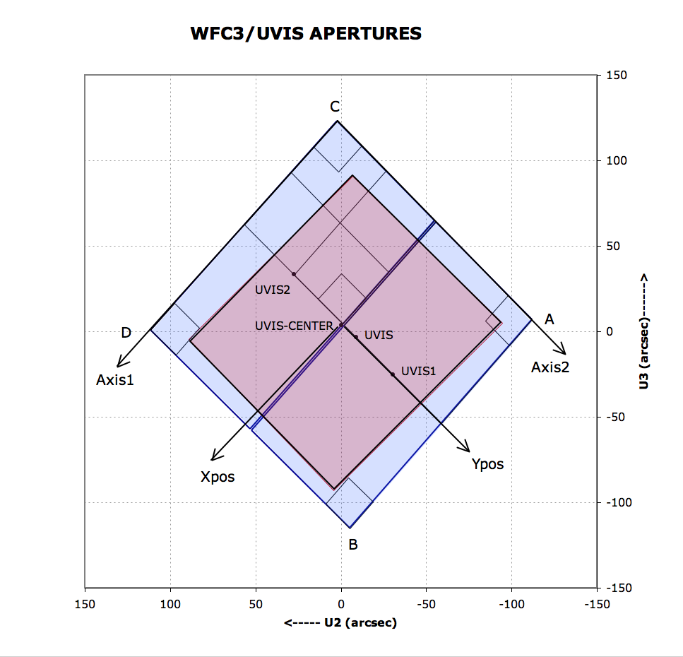
The POS TARG reference frame, sometimes referred to as the spacecraft system, is used for specifying the placement of an astronomical target relative to the aperture reference point (sometimes called the fiducial point) in the instrument field of view. Its units are arcseconds. For the UVIS channel, the POS TARG system is defined such that the POS TARG Y axis is aligned with Axis2 at the reference point of the aperture in use. The POS TARG X axis is by definition orthogonal to the POS TARG Y axis; it is not aligned with Axis1 due to geometric distortion.
As is the case for other HST instruments, the POS TARG origin is defined to be at the reference point (fiducial point) of the user-selected UVIS aperture (such as the geometric center of a particular chip, or the optimum center of a quadrant, etc.; see Table 6.1 below for the names of the various UVIS channel apertures). Figure 6.1 illustrates the POS TARG reference frame for the “UVIS” aperture, whose center is near the middle of the WFC3 UVIS field of view; the POS TARG directions are indicated by arrows labeled Xpos and Ypos.
The HST-based, or vehicle (V2, V3), system is an orthogonal reference frame tied to the telescope and is used operationally for alignment, pointing, and slewing purposes. The V1 axis lies along the optical axis while V2,V3 run parallel and perpendicular, respectively, to the HST solar-array rotation axis (see Figure 2.2). Note that the (undistorted) diagonals of the WFC3 CCD detector run along the V2,V3 directions. Because WFC3 is situated on-axis, the origin of the V2,V3 system lies near the center of the WFC3 field of view. However, the V2,V3 (and U2, U3) coordinate axes have been shifted for clarity in Figure 6.1. HST observers may be more familiar with the U2,U3 coordinate system than V2,V3; for example, the specification of the ORIENT angle Special Requirement in APT uses the position angle of the U3 axis. The U2,U3 coordinates are defined as U2 = –V2 and U3 = –V3, and are marked in Figure 6.1. Observations of an astrometric field were made to locate the detector in the (V2, V3) system (WFC3 ISR 2009-35).
A fourth coordinate system (the detector-based reference frame in pixel units) is described here for completeness, but observers are unlikely to encounter this system other than in technical documents created during the development and ground-testing of WFC3. The detector-based system (Xdet, Ydet) is used by the flight software for commanding the detectors. It is a right-handed system based upon the orientation of the CCD serial registers, with its origin at Amplifier A (the four amplifiers are in the outer corners of the detectors, as shown in Figure 6.1). The +Xdet and +Ydet axes map to the –Axis2 and +Axis1 axes, respectively. Unlike the image-based Axis1, Axis2 system, the detector system is 0-indexed. Parallel shifting is performed along constant Xdet, and serial shifting is done along the constant Ydet direction (Section 6.7.2).
6.4.4 Subarrays and On-Chip Binning
While the default WFC3 UVIS readout mode is full-frame (i.e., both CCD chips), subarrays may be employed to read out and store only a portion of a CCD. Subarrays may be used, for example, in cases where the full-field data-volume and/or instrument-overhead requirements would overly constrain the observations. There are also circumstances in which on-chip binning may be desirable, although note that when post-flash is necessary to mitigate CTE, binned mode is no longer advantageous (as discussed below). Both subarray and binned mode have implications for the inclusion of physical overscan information in the readout, as listed in Table 6.1 and discussed in Section 6.7.2.
Subarrays
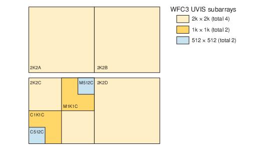
Since 2010 (Cycle 18), a wide range of subarray sizes have been available: 512 × 512, 1k × 1k, and 2k × 2k. User-defined subarrays, and subarrays that span quadrant boundaries, are no longer supported. Subarrays are invoked via the appropriate Aperture parameter in the Phase II observing proposal; these apertures contain the string “SUB” in their names. Figure 6.2 shows the supported subarrays. See Section 6.4.5 and Table 6.1 for the reference points (default target positions) of these apertures.
Figure 6.2: WFC3/UVIS subarrays. See text for reasons to prefer quadrant C. Full names of the subarrays are given in Table 6.1.
For the special case of quad filters (which are optical elements that provide four different bandpasses, one bandpass per WFC3 UVIS quadrant), the observer must select one of the “QUAD” Aperture values in the Phase II proposal, in conjunction with the desired quad filter via the filter parameter. This combination of quad aperture and quad filter ensures that the target is automatically placed in the correct quadrant for imaging with the requested quad bandpass. Furthermore, specification of the subarray quad aperture (UVIS-QUAD-SUB) instructs the ground system to read out only the 2k × 2k quadrant of interest. If “-SUB” is omitted from the quad aperture name (i.e., UVIS-QUAD, UVIS-QUAD-FIX), the target is positioned in the proper quadrant for the bandpass requested in the filter parameter, but the entire frame, both CCDs, is still read out. Table 6.1 indicates which apertures place the target at the geometric center of the subarray, and which apertures place it at a substantial offset from the center. See the Phase II Proposal Instructions for updates in aperture definitions at the beginning of a new Cycle.
Use of any quad filter aperture, full-frame or subarray, is fully supported. However, if data volume and overhead time are not an issue, the observer is encouraged to allow full-frame readouts of quad-filter exposures, enabling serendipitous discoveries in the other quadrants of the image as well as enrichment of the HST data archive.
On-Chip Binning
The BIN optional parameter may be used in the observing proposal (see Section 6.2) to specify that the CCDs be read out in binned mode. Legal values for the parameter are NONE (the default), or 2 or 3, for 2× 2 and 3 × 3 on-chip binning, respectively. On-chip binning is only allowed with full-frame readouts; it may not be used in conjunction with any subarray mode. To perform on-chip binning, multiple rows are parallel-shifted into the serial register, which is shifted multiple pixels at a time into a single output pixel, which is then read once. For the reasons discussed below, on-chip binning has not been useful for most programs, especially since the introduction of post-flash.
One advantage of on-chip binning is that it reduces the readout noise: a 2 × 2 or 3 × 3 binned pixel contains approximately the same amount of read noise as a single pixel in an unbinned readout (see Section 5.4.7), but 4 times or 9 times the signal. However, binning increases the fraction of the image affected by cosmic rays and by the ever-increasing number of hot pixels (see Section 5.4.9). Moreover, if the background in an exposure is so low that read noise is a significant concern, then CTE losses, which are also ever-increasing over time, will make faint sources difficult or impossible to detect. CTE losses can be reduced by using post-flash to increase the background by a selected number of electrons per unbinned pixel (see Section 6.2), ideally bringing the total background up to a level of ~20 electrons/pixel (see Section 6.9). Note that the post-flash is applied before the readout, so if binning and post-flash were to be used together, a post-flash of 20 electrons per pixel would put 80 electrons into a 2 × 2 binned pixel, and 180 electrons into a 3 × 3 binned pixel, with an accompanying increase in noise. The reduction in read noise due to binning would then have a minor effect on the overall signal-to-noise (Section 9.6), not worth the disadvantages of binning.
On-chip binning does reduce the data volume, which affects the management of buffer dumps. Buffer dumps of unbinned full frame exposures can be done in parallel to the exposures only for exposure times of 348 sec or longer. Shorter unbinned exposures require serial buffer dumps, using up valuable time during an orbit. Use of the binned modes can reduce or eliminate the time devoted to serial buffer dumps during an orbit, and thus increase the number of exposures that can be fit into an orbit. For example, the number of 100 sec exposures that can be executed in a typical orbit is 6 for unbinned data, 12 for 2 × 2 binned data, and 19 for 3 × 3 binned data. This gain is, of course, achieved at the expense of spatial resolution of the already under-sampled PSF (see Section 6.6.2), at the cost of increasing the area affected by bad pixels and cosmic rays, as well as at the cost of a reduced signal-to-noise for images requiring post-flash. The optimum way to reduce data dumping time is to take unbinned exposures in a subarray large enough to contain the target.
In addition, binning affects the overscan data associated with an exposure. At the frame edges, some science and overscan pixels are binned together. Section 6.7.2 gives details concerning the rows and columns affected by binning mixed science and overscan data.
6.4.5 Apertures
The APERTURE parameter in the Phase II observing proposal defines two quantities: the active region of the detector to be read out (full frame or subarray), as well as the positioning of the target within the region (reference point). The default is to place the target at the reference point (also called the fiducial point) of the chosen aperture, but a POS TARG Special Requirement may be added to offset the target from this position.
With regard to pointing HST, there are two types of apertures: “fixed” and “optimum.” The fixed positions have reference points near the geometric center of the aperture in question, and, as the name implies, their locations will remain fixed in image-based coordinates for the life of the instrument. The “optimum” apertures have reference points that are offset from the geometric center (if the need arises) so as to avoid any known CCD features (e.g., bad column, quad filter edge effects) that might compromise the observation of a target at that position. The locations of the “optimum” aperture reference points—in both the image-based coordinate system and the spacecraft V2,V3 coordinate system—may change over time as the characteristics and the characterization of the CCD evolve.
For updates on subarray and aperture definitions, check the Science Instrument Aperture File (SIAF) page. |
The choice of optimum or fixed aperture depends on the program’s objectives and target. For a very small target, or one which easily fits into the aperture’s field of view, the optimum aperture’s reference point is defined to ensure that the target center does not fall on known problematic areas of the detector. The WFC3 website and STAN will announce changes in optimum aperture definitions. On the other hand, when the observer needs precise control of the position of the target on the detector, fixed apertures should be used. Fixed apertures are therefore appropriate when target position relative to detector edges is important, or when mosaics are being designed with edges requiring positional accuracies of better than 10 arcsec or so. The available WFC3 UVIS apertures (Table 6.1) include both fixed and optimum versions for the primary locations: near the center of the full two-chip detector (UVIS and UVIS-FIX), and at the center of each chip (UVIS1 and UVIS2, and UVIS1-FIX and UVIS2-FIX). The aperture UVIS-CENTER places the target in or on the edge of the interchip gap; although it is not a FIX aperture, a change in the definition of this aperture is not expected.
For faint targets, users are cautioned against using the apertures UVIS or UVIS-FIX, which put the target near the center of the array. In these regions, CTE losses are high due to the large number of pixel transfers required to read out the detector. For full-frame exposures, users may wish to instead use apertures UVIS2-C512C-CTE or UVIS2-C1K1C-CTE. These apertures were introduced for Cycle 23 (Oct 2015). The UVIS*CTE apertures place the target near the C amplifier at the same reference positions as the optimum aperture subarrays UVIS2-C512C-SUB and UVIS2-C1K1C-SUB, respectively, and will read out the full 2-chip frame.
There are fixed and optimum apertures for use with the quad filters. Because the filter wheel assembly is necessarily offset from the focal plane, the edges between quad filters are blurred at the focal plane, producing regions with contributions from multiple quad filter passbands (Figure 6.8). The UVIS-QUAD-SUB apertures (redefined for Cycle 20, Oct 2012) and UVIS-QUAD apertures have reference points centered within the useful single-passband regions, while the UVIS-QUAD-FIX apertures have reference points at the geometric centers of the quadrants (closer to the filter edge effects). In programs where targets are placed in different quadrants, the choice of quad aperture will affect the size of offsets and may require new guide star acquisition, as described in Section 10.2.
Subarray apertures pictured in Figure 6.2 are all “optimum”; no “fixed” apertures are available for these subarrays. The reference points for these apertures have initially been defined near the geometric center of the subarray, except for the 2K2 apertures, where the reference points match those of the UVIS-QUAD apertures.
Table 6.1: Predefined apertures for WFC3/UVIS (see also the Phase II Proposal Instructions).
Aperture | Over- scan1 | Region | Reference (fiducial) point |
UVIS | P, V | Full detector | Optimum point near center (displaced from interchip gap) of full two-CCD field of view |
UVIS-CENTER | P, V | Full detector | Geometric center of full two-CCD field of view |
UVIS-FIX | P, V | Full detector | Near geometric center (displaced from interchip gap) of full two-CCD field of view |
UVIS1 | P, V | Full detector | Optimum point near center of CCD Chip 1 |
UVIS1-FIX | P, V | Full detector | Geometric center of CCD Chip 1 |
UVIS2 | P, V | Full detector | Optimum point near center of CCD Chip 2 |
UVIS2-FIX | P, V | Full detector | Geometric center of CCD Chip 2 |
UVIS-IR-FIX | P, V | Full detector | Pointing matched to IR-FIX aperture in Table 7.1 |
G280-REF2 | P, V | Full detector | Reference point for undispersed exposures (coincides with reference point of exposures made with the G280 grism) |
UVIS-QUAD | P, V | Full detector | Optimum point in the quadrant corresponding to the selected quadrant filter (offset from the center of the quadrant toward the nearest corner of the detector by about 8 to 10 arcsec in X and in Y; see Figure 6.8) |
UVIS-QUAD-FIX | P, V | Full detector | Geometric center of quadrant corresponding to selected quadrant filter |
UVIS2-C1K1C-CTE | P, V | Full detector | Same as UVIS2-C1K1C-SUB (see below), for better CTE performance |
UVIS2-C512C-CTE | P, V | Full detector | Same as UVIS2-C512C-SUB (see below), for better CTE performance |
UVIS-QUAD-SUB | P | 2047 × 2050 on the quadrant corresponding to selected quadrant filter | Same as UVIS-QUAD (optimum point in the relevant quadrant) starting in Cycle 20 in Oct 2012 (prior to that, the reference point was the geometric center of the quadrant) |
UVIS1-2K2A-SUB | P | 2047 × 2050 | Optimum point for the corresponding quadrant filter FQ* (for matching N,M,W filter exposures to UVIS-QUAD or UVIS-QUAD-SUB aperture exposures), about 14 arcsec from the center of the 2k × 2k subarray. If not pairing with FQ* quadrant filter exposures, UVIS2-2K2C-SUB is preferred (Section 6.4.4). |
UVIS2-M1K1C-SUB | none | 1024 × 1024, quadrant C near detector center | Optimum point near center of 1k × 1k subarray |
UVIS2-C1K1C-SUB | P | 1025 × 1024, near Amplifier C | Optimum point near center of 1k × 1k subarray |
UVIS2-M512C-SUB | none | 512 × 512, quadrant C near detector center | Optimum point near center of 512 × 512 subarray |
UVIS2-C512C-SUB | P | 513 ×512, near amplifier C | Optimum point near center of 512 × 512 subarray |
1 "P" indicates aperture includes physical overscan, "V" indicates aperture includes virtual overscan.
2See Section 8.2 for information on the use of the G280-REF aperture.
-
WFC3 Instrument Handbook
- • Acknowledgments
- Chapter 1: Introduction to WFC3
- Chapter 2: WFC3 Instrument Description
- Chapter 3: Choosing the Optimum HST Instrument
- Chapter 4: Designing a Phase I WFC3 Proposal
- Chapter 5: WFC3 Detector Characteristics and Performance
-
Chapter 6: UVIS Imaging with WFC3
- • 6.1 WFC3 UVIS Imaging
- • 6.2 Specifying a UVIS Observation
- • 6.3 UVIS Channel Characteristics
- • 6.4 UVIS Field Geometry
- • 6.5 UVIS Spectral Elements
- • 6.6 UVIS Optical Performance
- • 6.7 UVIS Exposure and Readout
- • 6.8 UVIS Sensitivity
- • 6.9 Charge Transfer Efficiency
- • 6.10 Other Considerations for UVIS Imaging
- • 6.11 UVIS Observing Strategies
- Chapter 7: IR Imaging with WFC3
- Chapter 8: Slitless Spectroscopy with WFC3
-
Chapter 9: WFC3 Exposure-Time Calculation
- • 9.1 Overview
- • 9.2 The WFC3 Exposure Time Calculator - ETC
- • 9.3 Calculating Sensitivities from Tabulated Data
- • 9.4 Count Rates: Imaging
- • 9.5 Count Rates: Slitless Spectroscopy
- • 9.6 Estimating Exposure Times
- • 9.7 Sky Background
- • 9.8 Interstellar Extinction
- • 9.9 Exposure-Time Calculation Examples
- Chapter 10: Overheads and Orbit Time Determinations
-
Appendix A: WFC3 Filter Throughputs
- • A.1 Introduction
-
A.2 Throughputs and Signal-to-Noise Ratio Data
- • UVIS F200LP
- • UVIS F218W
- • UVIS F225W
- • UVIS F275W
- • UVIS F280N
- • UVIS F300X
- • UVIS F336W
- • UVIS F343N
- • UVIS F350LP
- • UVIS F373N
- • UVIS F390M
- • UVIS F390W
- • UVIS F395N
- • UVIS F410M
- • UVIS F438W
- • UVIS F467M
- • UVIS F469N
- • UVIS F475W
- • UVIS F475X
- • UVIS F487N
- • UVIS F502N
- • UVIS F547M
- • UVIS F555W
- • UVIS F600LP
- • UVIS F606W
- • UVIS F621M
- • UVIS F625W
- • UVIS F631N
- • UVIS F645N
- • UVIS F656N
- • UVIS F657N
- • UVIS F658N
- • UVIS F665N
- • UVIS F673N
- • UVIS F680N
- • UVIS F689M
- • UVIS F763M
- • UVIS F775W
- • UVIS F814W
- • UVIS F845M
- • UVIS F850LP
- • UVIS F953N
- • UVIS FQ232N
- • UVIS FQ243N
- • UVIS FQ378N
- • UVIS FQ387N
- • UVIS FQ422M
- • UVIS FQ436N
- • UVIS FQ437N
- • UVIS FQ492N
- • UVIS FQ508N
- • UVIS FQ575N
- • UVIS FQ619N
- • UVIS FQ634N
- • UVIS FQ672N
- • UVIS FQ674N
- • UVIS FQ727N
- • UVIS FQ750N
- • UVIS FQ889N
- • UVIS FQ906N
- • UVIS FQ924N
- • UVIS FQ937N
- • IR F098M
- • IR F105W
- • IR F110W
- • IR F125W
- • IR F126N
- • IR F127M
- • IR F128N
- • IR F130N
- • IR F132N
- • IR F139M
- • IR F140W
- • IR F153M
- • IR F160W
- • IR F164N
- • IR F167N
- Appendix B: Geometric Distortion
- Appendix C: Dithering and Mosaicking
- Appendix D: Bright-Object Constraints and Image Persistence
-
Appendix E: Reduction and Calibration of WFC3 Data
- • E.1 Overview
- • E.2 The STScI Reduction and Calibration Pipeline
- • E.3 The SMOV Calibration Plan
- • E.4 The Cycle 17 Calibration Plan
- • E.5 The Cycle 18 Calibration Plan
- • E.6 The Cycle 19 Calibration Plan
- • E.7 The Cycle 20 Calibration Plan
- • E.8 The Cycle 21 Calibration Plan
- • E.9 The Cycle 22 Calibration Plan
- • E.10 The Cycle 23 Calibration Plan
- • E.11 The Cycle 24 Calibration Plan
- • E.12 The Cycle 25 Calibration Plan
- • E.13 The Cycle 26 Calibration Plan
- • E.14 The Cycle 27 Calibration Plan
- • E.15 The Cycle 28 Calibration Plan
- • E.16 The Cycle 29 Calibration Plan
- • E.17 The Cycle 30 Calibration Plan
- • E.18 The Cycle 31 Calibration Plan
- • E.19 The Cycle 32 Calibration Plan
- • E.20 The Cycle 33 Calibration Plan
- • Glossary