4.4 The SBC MAMA
4.4.1 MAMA Properties
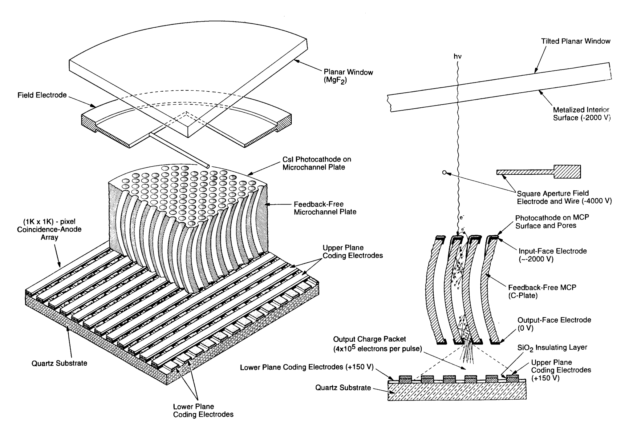
The ACS MAMA detector is the STIS flight spare STF7, providing coverage from 1150 Å to 1700 Å. MAMA detectors are photon-counting devices which process events serially. The ACS MAMA only operates in the accumulate (ACCUM) mode, in which a time-integrated image is produced. Unlike the STIS MAMAs, ACS does not offer the high-resolution (2048 × 2048) mode or time-tagged data acquisition. Figure 4.13 illustrates the design of the MAMA, which has an opaque CsI photocathode deposited directly on the face of the curved microchannel plate (MCP). Target photons strike the photocathode, liberating single photoelectrons which pass into the MCP, where a pulse of ~4 × 10⁵ e¯ is generated. The pulse is recorded by an anode array behind the photocathode and detected by the MAMA electronics which reject false pulses and determine the position of the photon event on the detector.
The field electrode, or repeller wire, repels electrons emitted from the microchannel plate back into the channels. This provides an increase in quantum efficiency of the detector at the price of an increase in the detector point spread function halo. The repeller wire voltage is always on for SBC observations.
The ACS MAMA has a broken anode which disables rows 600 to 605. There are three dark spots smaller than 50 μm at positions (334,977), (578,964), and (960,851), as well as two bright spots at (55,281) and (645,102) with fluctuating rates that are always less than three counts per second. The reference pixel has been moved to (512,400) to avoid these areas (see Table 7.10).
Table 4.7: SBC detector performance characteristics.
Characteristic | SBC MAMA performance |
|---|---|
Photocathode | CsI |
Wavelength range | ~1150 to 1700 Å |
Pixel format | 1024 × 1024 pixel |
Pixel size | 25 × 25 μm2 |
Plate scale | ~0.034 × 0.030 arcsec2/pixel |
Field of view | 34.6 × 30.5 arcsec2 |
Quantum efficiency | ~34% @ 1216 Å |
Dark count [a] | 8.52 × 10⁻⁶ counts/s/pixel |
Global count-rate linearity limit | 200,000 counts/s |
Local count-rate linearity limit [b] | ~22 counts/s/pixel |
Visible light DQE | < 1.2 × 10⁻⁹ above 400 nm |
a The dark current remains constant up to an instrument temperature ~25°C. Above that temperature, the dark current increases rapidly.
b Rate at which counting shows 1% deviation from linearity.
4.4.2 SBC Spectral Response
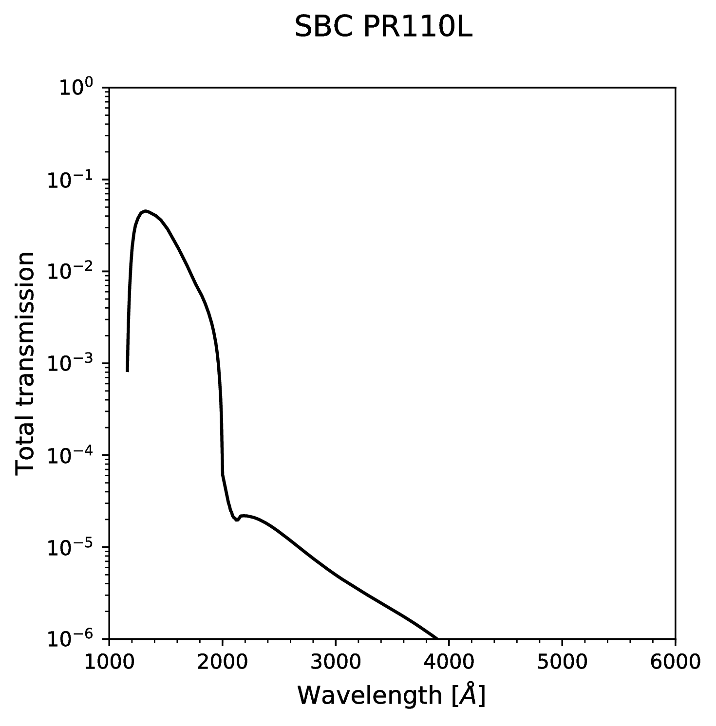
The total transmission curve for the SBC with the PR110L prism is shown in Figure 4.14. The peak photocathode response occurs at Lyman-α. Its spectral response is defined by the cutoff of the MgF2 window at 1150 Å at short wavelengths, and by the relatively steep decline of the CsI photocathode at long wavelengths.
Observations of flux calibration stars and a G-type star using the SBC PR110L prism have revealed that the sensitivity of the MAMA detector to optical and near-UV light is apparently much larger than previously thought (ACS TIR 2008-021).
Estimates of the real SBC throughput indicates that the detector efficiency is factors of approximately 50 and 1000 higher at wavelengths of 3000 Å and 4000 Å respectively compared to ground testing. For a solar type spectrum, this can mean that one-half or more of the counts detected are due to optical and near-UV photons, rather than from the expected FUV photons. The updated sensitivity curve has been incorporated both in the Exposure Time Calculator (ETC) and in the instrument throughput tables. There is also some evidence that this red leak changes as the SBC detector warms up, increasing by as much as 30% over the course of five orbits. It is not yet clear if this red leak has also been increasing secularly over time. STIS FUV MAMA data seem to show a similar, although perhaps somewhat smaller effect.
For dispersed PR110L and PR130L observations, it is straightforward to identify this extra red light; however, it clearly also affects SBC imaging observations done with the long pass filters. Until this effect is better understood and calibrated, extreme caution should be used when interpreting FUV imaging observations of red targets. Observers who need to measure FUV fluxes of red targets are strongly recommended to take interleaving observations with two different SBC long pass filters (e.g., F140LP and F165LP), so that the difference in the count rates can be used to isolate the true FUV flux. There is some recent evidence that the red leak is temperature dependent and cannot be accurately determined in the F165LP filter. For this reason it is recommended that this filter not be used for science. It should only be used in conjunction with other filters to subtract red photons from the measurements in other bandpasses.
4.4.3 Optical Performance
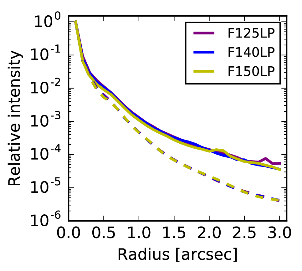
The SBC exhibits low-level extended wings in the detector point-spread function (PSF) (ACS ISR 2016-05). Sample MAMA detector PSF profiles are shown in Figure 4.15.
-
ACS Instrument Handbook
- • Acknowledgments
- • Change Log
- • Chapter 1: Introduction
- Chapter 2: Considerations and Changes After SM4
- Chapter 3: ACS Capabilities, Design and Operations
- Chapter 4: Detector Performance
- Chapter 5: Imaging
- Chapter 6: Polarimetry, Coronagraphy, Prism and Grism Spectroscopy
-
Chapter 7: Observing Techniques
- • 7.1 Designing an ACS Observing Proposal
- • 7.2 SBC Bright Object Protection
- • 7.3 Operating Modes
- • 7.4 Patterns and Dithering
- • 7.5 A Road Map for Optimizing Observations
- • 7.6 CCD Gain Selection
- • 7.7 ACS Apertures
- • 7.8 Specifying Orientation on the Sky
- • 7.9 Parallel Observations
- • 7.10 Pointing Stability for Moving Targets
- Chapter 8: Overheads and Orbit-Time Determination
- Chapter 9: Exposure-Time Calculations
-
Chapter 10: Imaging Reference Material
- • 10.1 Introduction
- • 10.2 Using the Information in this Chapter
-
10.3 Throughputs and Correction Tables
- • WFC F435W
- • WFC F475W
- • WFC F502N
- • WFC F550M
- • WFC F555W
- • WFC F606W
- • WFC F625W
- • WFC F658N
- • WFC F660N
- • WFC F775W
- • WFC F814W
- • WFC F850LP
- • WFC G800L
- • WFC CLEAR
- • HRC F220W
- • HRC F250W
- • HRC F330W
- • HRC F344N
- • HRC F435W
- • HRC F475W
- • HRC F502N
- • HRC F550M
- • HRC F555W
- • HRC F606W
- • HRC F625W
- • HRC F658N
- • HRC F660N
- • HRC F775W
- • HRC F814W
- • HRC F850LP
- • HRC F892N
- • HRC G800L
- • HRC PR200L
- • HRC CLEAR
- • SBC F115LP
- • SBC F122M
- • SBC F125LP
- • SBC F140LP
- • SBC F150LP
- • SBC F165LP
- • SBC PR110L
- • SBC PR130L
- • 10.4 Geometric Distortion in ACS
- • Glossary


