5.1 Imaging Overview
HRC has been unavailable since January 2007. Information regarding HRC is provided for archival purposes.
WFC may be offered as shared risk in Cycle 34 and receive minimal support and calibration. See the ACS website, Call for Proposals, and OPCR webpage for the latest status.
ACS has been used to obtain images through a variety of optical and ultraviolet filters. The CCD filter wheels contain filters of two different sizes. Some filters (F435W, F475W, F502N, F550M, F555W, F606W, F625W, F658N, F660N, F775W, F814W, F850LP, and G800L) are full-sized filters that can be used with both WFC and HRC. Others (F220W, F250W, F330W, F344N, F892N, POL0UV, POL60UV, POL120UV, POL0V, POL60V, POL120V, and PR200L) are smaller, giving a full un-vignetted field of view when used with the HRC, but a vignetted field of view of only 72 × 72 arcsec2 when used with the WFC. Use of the small UV filters with WFC is not supported due to the unpredictable behavior of the silver coating shortward of 4000 Å.
For WFC and HRC imaging, the desired filter in one filter wheel is rotated into position and a CLEAR aperture in the other filter wheel is automatically selected, see Figures 3.2 and 3.3. (Users need not specify CLEAR in their HST proposals.) For SBC imaging, the single filter wheel is rotated to the desired position. Every third spot (#1, 4, 7, 10) in the SBC filter wheel is opaque, so the wheel must only be rotated to an adjacent slot to block the beam if a bright object limit violation occurs. Tables 5.1, 5.2, and 5.3 summarize the filters available for imaging with each channel. Figures 5.1 through 5.6 show the filter transmission curves. Figures 5.10 and 5.12 show the location of the filters in each filter wheel. Figure 5.7 shows the integrated system throughputs. Please visit the ACS System Throughputs webpage or refer to Chapter 10 for total system throughputs for each ACS filter and dispersing element.
The ACS ramp filters are designed to allow narrow- or medium-band imaging centered at an arbitrary wavelength. Each ramp filter is divided into three segments, each of which can be used with the WFC while only the middle segment was used with the HRC. See Table 5.2 for the list of available ramp filters. More information is available in Section 7.3.1, and schematics of the ramp filters and apertures are given in Figures 7.4 and 7.5.
Filterless WFC or HRC is available, but unsupported, by specifying CLEAR as the filter name. Rough wavelengths and bandwidths for CLEAR imaging are listed in Table 5.1. CLEAR imaging yields significantly degraded WFC PSFs, but only slightly degraded HRC PSFs. See ACS ISR 2003-03 for more details about CLEAR imaging.
Table 5.1: ACS WFC/HRC filters in Filter Wheel #1.
(HRC information is provided for archival purposes only.)
Filter | Central | Width | Description | Camera |
|---|---|---|---|---|
CLEAR | 6200 | 5200 | Clear aperture | WFC/HRC |
F555W | 5346 | 1193 | Johnson V | WFC/HRC |
F775W | 7764 | 1528 | SDSS i | WFC/HRC |
F625W | 6318 | 1442 | SDSS r | WFC/HRC |
F550M | 5580 | 547 | Narrow V | WFC/HRC |
F850LP | 9445 | 1229 | SDSS z | WFC/HRC |
POL0UV | 2000 to 6000 | – | 0° UV polarizer | HRC[/WFC] [a] |
POL60UV | 2000 to 6000 | – | 60° UV polarizer | HRC[/WFC] [a] |
POL120UV | 2000 to 6000 | – | 120° UV polarizer | HRC[/WFC] [a] |
F892N | 8917 | 154 | Methane (2%) | HRC[/WFC] [a] |
F606W | 5907 | 2342 | Broad V | WFC/HRC |
F502N | 5022 | 57 | [OIII] (1%) | WFC/HRC |
G800L | 5800 to 11,000 | – | Grism (R ~100) | WFC/HRC |
F658N | 6584 | 78 | Hα (1%) | WFC/HRC |
F475W | 4760 | 1458 | SDSS g | WFC/HRC |
a [/WFC] indicates that polarizer filters and F892N, designed for the HRC field of view, induce vignetting when used with the WFC, producing a 72 × 72 arcsec2 field of view.
Table 5.2: ACS WFC/HRC filters in Filter Wheel #2.
(Information regarding the HRC is provided for archival purposes only.).
Filter | Central | Width | Description | Camera |
|---|---|---|---|---|
CLEAR | 6000 | 5200 | Clear aperture | WFC/HRC |
F660N | 6602 | 40 | [NII] (1%) | WFC/HRC |
F814W | 8333 | 2511 | Broad I | WFC/HRC |
FR388N | 3710 to 4050 | 2%[a] | [OII] Ramp—middle segment | WFC/HRC |
FR423N | 4050 to 4420 | 2% [a] | [OII] Ramp—inner segment | WFC |
FR462N | 4420 to 4820 | 2% [a] | [OII] Ramp—outer segment | WFC |
F435W | 4297 | 1038 | Johnson B | WFC/HRC |
FR656N | 6270 to 6850 | 2% [a] | Hα Ramp—middle segment | WFC/HRC |
FR716N | 6850 to 7470 | 2% [a] | Hα Ramp—inner segment | WFC |
FR782N | 7470 to 8160 | 2% [a] | Hα Ramp—outer segment | WFC |
POL0V | 4000 to 8000 | – | 0° Visible Polarizer | HRC[/WFC] [b] |
F330W | 3354 | 588 | HRC U | HRC |
POL60V | 4000 to 8000 | – | 60° Visible Polarizer | HRC[/WFC] [b] |
F250W | 2696 | 549 | Near-UV broadband | HRC |
POL120V | 4000 to 8000 | – | 120° Visible Polarizer | HRC[/WFC] [b] |
PR200L | 2000 to 4000 | – | NUV Prism (R~100 @ 200 nm) | HRC |
F344N | 3434 | 60 | Ne V (2%) | HRC |
F220W | 2228 | 485 | Near-UV broadband | HRC |
FR914M | 7570 to 10,710 | 9% [a] | Broad Ramp—middle segment | WFC/HRC |
FR853N | 8160 to 8910 | 2% [a] | IR Ramp—inner segment | WFC |
FR931N | 8910 to 9720 | 2% [a] | IR Ramp—outer segment | WFC |
FR459M | 3810 to 5370 | 9% [a] | Broad Ramp—middle segment | WFC/HRC |
FR647M | 5370 to 7570 | 9% [a] | Broad Ramp—inner segment | WFC |
FR1016N | 9720 to 10,610 | 2% [a] | IR Ramp—outer segment | WFC |
FR505N | 4820 to 5270 | 2% [a] | [OIII] Ramp—middle segment | WFC/HRC |
FR551N | 5270 to 5750 | 2% [a] | [OIII] Ramp—inner segment | WFC |
FR601N | 5750 to 6270 | 2% [a] | [OIII] Ramp—outer segment | WFC |
aThe width of the ramp filters is a percentage relative to the central wavelength of the bandpass, Δλ/λ.
b [/WFC] indicates that polarizer filters, designed for the HRC field of view, induce vignetting when used with the WFC, producing a 72 × 72 arcsec2 field of view.
Table 5.3: ACS SBC filter complement.
Filter name | Description |
|---|---|
F115LP | MgF2 (1150 Å longpass) |
F125LP | CaF2 (1250 Å longpass) |
F140LP | BaF2 (1400 Å longpass) |
F150LP | Crystal quartz (1500 Å longpass) |
F165LP | Fused Silica (1650 Å longpass) |
F122M | Lyα (λ = 1200 Å, Δλ = 60 Å) |
PR110L | LiF Prism (R~100) |
PR130L | CaF2 Prism (R~100) |
Figure 5.1: ACS broad-band filters.
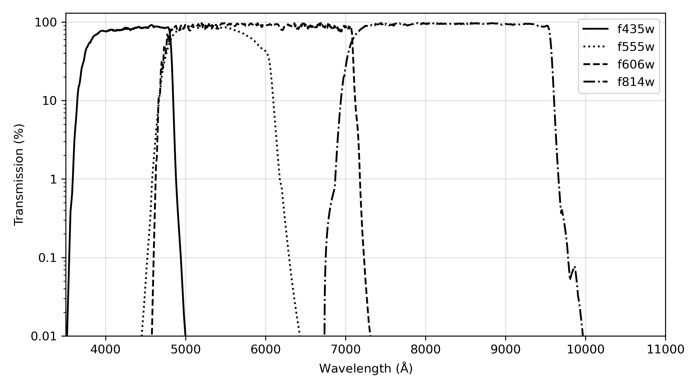
Figure 5.2: ACS SDSS filters.
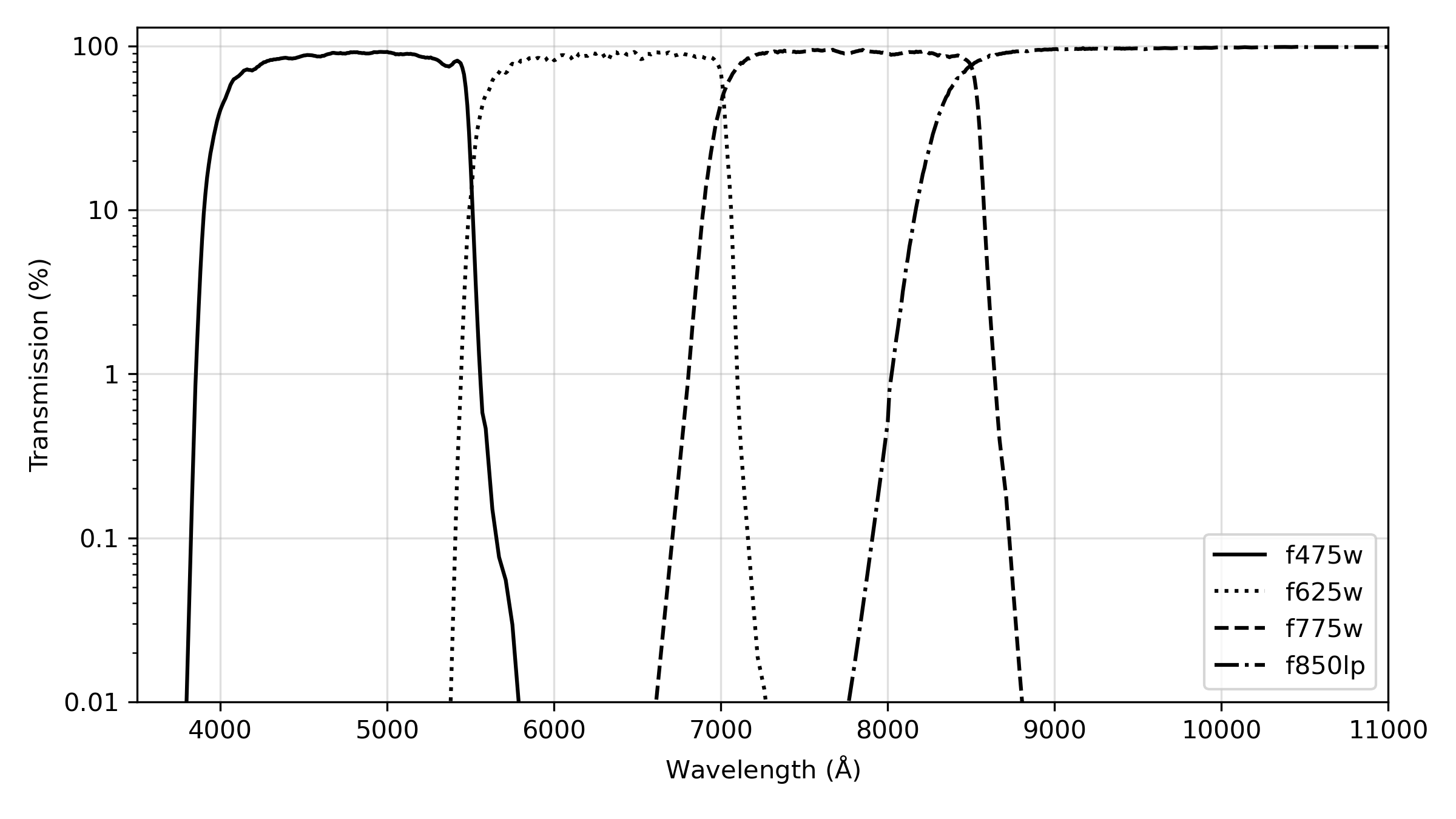
Figure 5.3: ACS UV and medium-band filters.
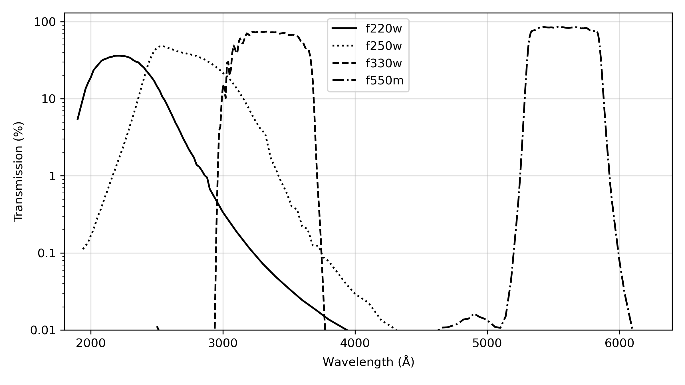
Figure 5.4: ACS narrow band filters.
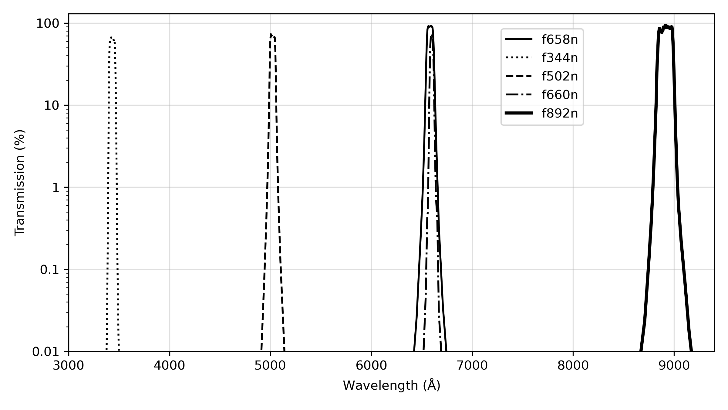
Figure 5.5: ACS SBC filters.
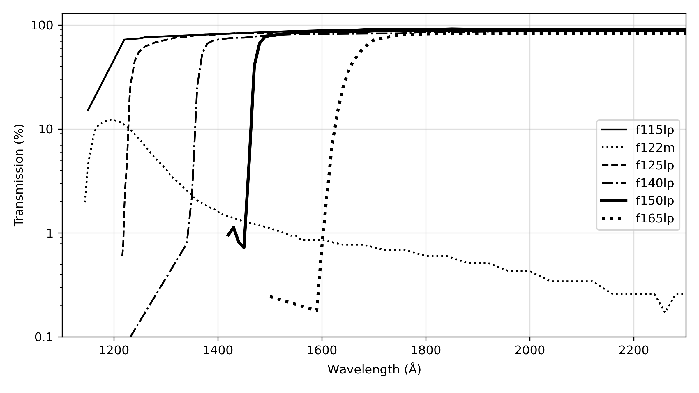
Figure 5.6: Comparison between the ACS and WFPC2 ramp filters.
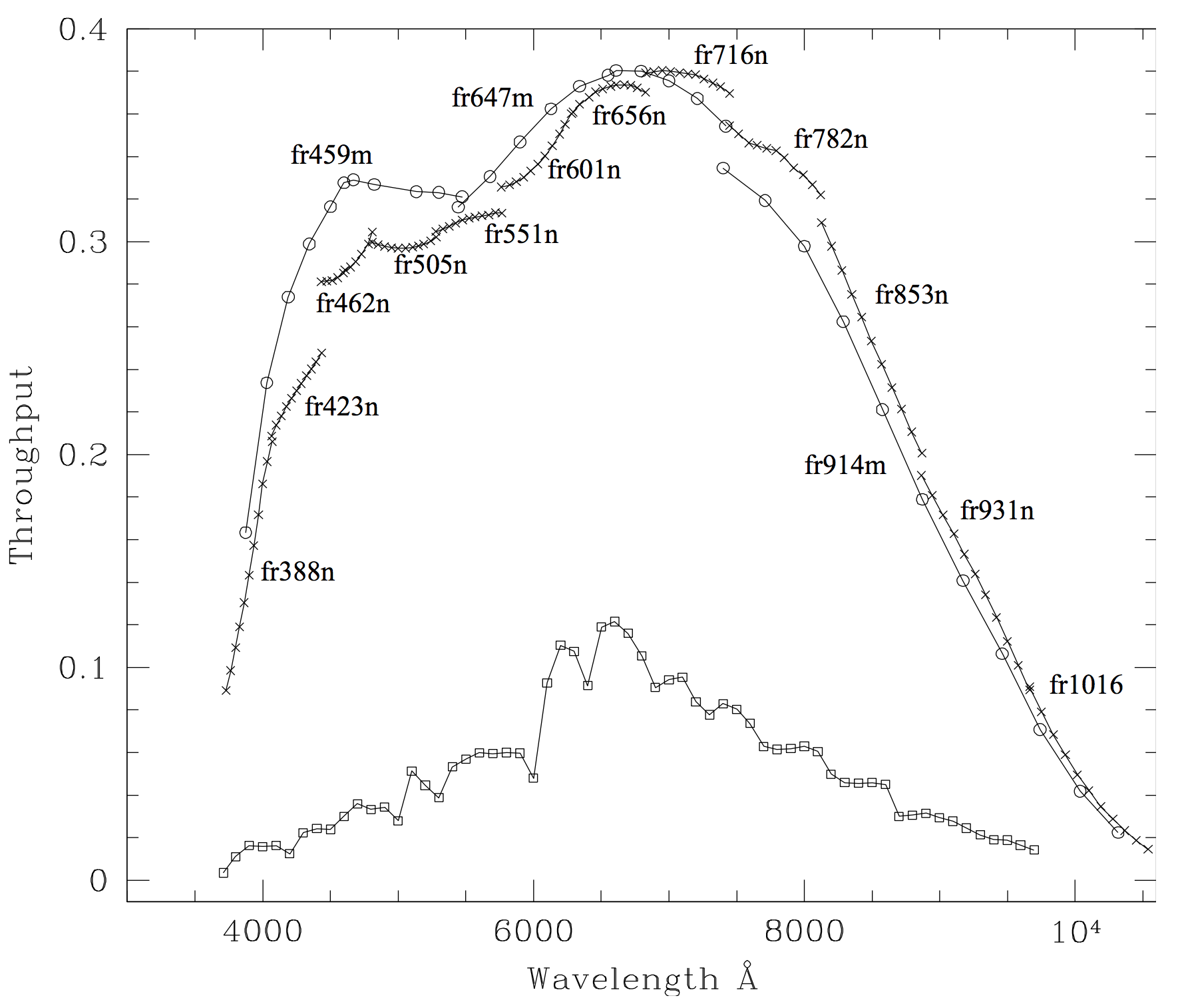
The crosses and open circles are the ACS narrow and medium band ramp filters. The open squares are the four WFPC2 ramp filters. For each of the ACS filters, the peak throughput for the central 11 wavelength points is plotted. For the WFPC2 filters, the peak throughput for every 100 Å within the field of view of any of the four chips and for a 0° filter rotation angle (as mapped in Figures 3.4 and 3.5 of the WFPC2 Instrument Handbook) is plotted.
-
ACS Instrument Handbook
- • Acknowledgments
- • Change Log
- • Chapter 1: Introduction
- Chapter 2: Considerations and Changes After SM4
- Chapter 3: ACS Capabilities, Design and Operations
- Chapter 4: Detector Performance
- Chapter 5: Imaging
- Chapter 6: Polarimetry, Coronagraphy, Prism and Grism Spectroscopy
-
Chapter 7: Observing Techniques
- • 7.1 Designing an ACS Observing Proposal
- • 7.2 SBC Bright Object Protection
- • 7.3 Operating Modes
- • 7.4 Patterns and Dithering
- • 7.5 A Road Map for Optimizing Observations
- • 7.6 CCD Gain Selection
- • 7.7 ACS Apertures
- • 7.8 Specifying Orientation on the Sky
- • 7.9 Parallel Observations
- • 7.10 Pointing Stability for Moving Targets
- Chapter 8: Overheads and Orbit-Time Determination
- Chapter 9: Exposure-Time Calculations
-
Chapter 10: Imaging Reference Material
- • 10.1 Introduction
- • 10.2 Using the Information in this Chapter
-
10.3 Throughputs and Correction Tables
- • WFC F435W
- • WFC F475W
- • WFC F502N
- • WFC F550M
- • WFC F555W
- • WFC F606W
- • WFC F625W
- • WFC F658N
- • WFC F660N
- • WFC F775W
- • WFC F814W
- • WFC F850LP
- • WFC G800L
- • WFC CLEAR
- • HRC F220W
- • HRC F250W
- • HRC F330W
- • HRC F344N
- • HRC F435W
- • HRC F475W
- • HRC F502N
- • HRC F550M
- • HRC F555W
- • HRC F606W
- • HRC F625W
- • HRC F658N
- • HRC F660N
- • HRC F775W
- • HRC F814W
- • HRC F850LP
- • HRC F892N
- • HRC G800L
- • HRC PR200L
- • HRC CLEAR
- • SBC F115LP
- • SBC F122M
- • SBC F125LP
- • SBC F140LP
- • SBC F150LP
- • SBC F165LP
- • SBC PR110L
- • SBC PR130L
- • 10.4 Geometric Distortion in ACS
- • Glossary