5.3 Wide Field Optical CCD Imaging
HRC has been unavailable since January 2007. Information about the HRC is provided for archival purposes. Please check for updates on the ACS website.
WFC may be offered as shared risk in Cycle 34 and receive minimal support and calibration. See the ACS website, Call for Proposals, and OPCR webpage for the latest status.
The Wide Field Channel (WFC) of ACS was designed primarily for high throughput observations at visible wavelengths. The use of protected silver mirror coatings, the small number of reflections, and the use of a red sensitive CCD have provided the high throughput required for this camera at the expense of a 3700 Å blue cutoff. The WFC detectors are two butted 2K × 4K thinned, backside-illuminated, SITe CCDs with a red optimized coating and long-λ halo fix. The plate scale is 0.050 arcseconds per pixel, which provides a good compromise between adequately sampling the PSF and a wide field of view. The WFC PSF is critically (Nyquist) sampled at 11,600 Å and undersampled by a factor of 3 at the blue end of the WFC sensitivity range (3700 Å). A final reconstructed FWHM of 0.100 to 0.140 arcseconds is possible for well-dithered observations. However, dithering will not be able to recover the full resolution of the optical system because the WFC PSF FWHM is largely dependent on the blurring caused by CCD charge diffusion (ACS ISR 2003-06). See Section 7.4 for more discussion of how to use dithered observations to optimally sample the PSF.
The optical design of the camera introduces a two-component geometric distortion. The detectors themselves are at an angle with respect to the optical axis. This produces an 8% stretching of one pixel diagonal compared to the other. As a result, WFC pixels project on the sky as rhombuses rather than squares. These effects are purely geometrical and are routinely corrected in the ACS data reduction pipeline. The second component of geometric distortion is more complex. This distortion causes up to ±9% variation in effective pixel area and needs to be taken into account when doing accurate photometry or astrometry as the effective area of the detector pixels varies nonlinearly with field position. See Section 10.4 for a detailed discussion of the distortion in ACS.
5.3.1 Filter Set
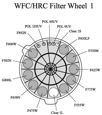
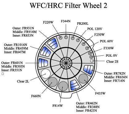
Figure 5.10 shows the filter wheels used by the WFC, and Tables 5.1 and 5.2 list the filter characteristics in more detail.
Figure 5.10: WFC and HRC filter wheels layout.
WFPC2 and Johnson-Cousins filters
All of the most commonly used WFPC2 filters are included in the ACS filter set. In addition to a medium and a broad V-band filter (F550M and F606W), there is a complete Johnson-Cousins BVI set (F435W, F555W, F814W).
Sloan Digital Sky Survey filters
The Sloan Digital Sky Survey (SDSS) griz filter set (F475W, F625W, F775W, F850LP) is designed to provide high throughput for the wavelengths of interest and excellent rejection of out-of-band wavelengths. The filters were designed to provide wide, non-overlapping filter bands that cover the entire range of CCD sensitivity from blue to near-IR wavelengths.
Narrow Band filters
The Hα (F658N), [OIII] (F502N), and [NII] (F660N) narrow band filters are full-size, and therefore can be used with WFC (they were also used with HRC when it was operational). F344N and F892N were intended for use with HRC, and therefore are sized for the HRC field of view. F892N is available for use with WFC, but resulting images will be vignetted, as shown in Figure 5.11. WFC's sensitivity does not overlap with the F344N passband.
Figure 5.11: Schematic of F892N vignetting when used with WFC
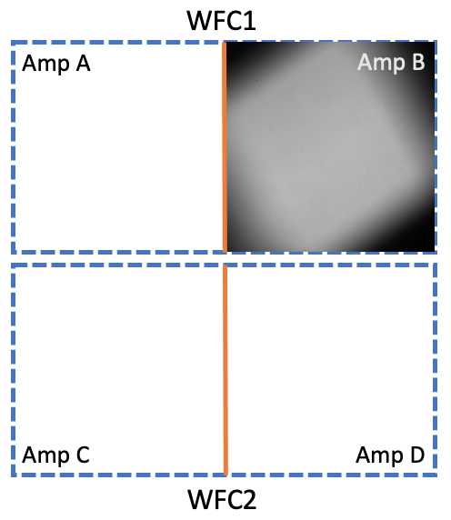
When used with WFC, the F892N filter results in a vignetted field of view as shown by this flat field exposure, j9v9wdavq. The F892N field of view is automatically placed on WFC1 in the quadrant read out by amp B, i.e., the WFC1-SMFL aperture. See Section 7.7.3 for more information. The remainder of the WFC detectors is shown as a dashed area for full-frame context.
Ramp filters
ACS includes a complete set of ramp filters that provide full coverage of the WFC wavelength range at 2% and 9% bandwidth. Each ramp filter consists of three segments. The inner and outer filter segments can be used with the WFC only, while the middle segments could be used by both WFC and HRC. Unlike the WFPC2, where the desired wavelength is achieved by offsetting the telescope, the wavelength of ACS ramps is selected by rotating the filter while the target is positioned in one of the pre-defined apertures. The monochromatic field of view of the ramp filters is approximately 40 × 80 arcsec2. Details of how to use the ramp filters are given in Section 7.3.
Polarizer filters
The WFC/HRC filter wheels contain polarizers with pass directions spaced by 60°, optimized for both the UV (POL0UV, POL60UV, and POL120UV) and the visible (POL0V, POL60V, and POL120V). All the polarizer filters are sized for the HRC field of view. They induce vignetting when used with the WFC, for which the FOV will be about 72 × 72 arcsec2, similar to that shown in Figure 5.11. More information on the use of the polarizers is given in Chapter 6.
Grism and Prism
The CCD channels also have a grism (G800L) for use with both WFC and HRC from 5500 Å to 10,500 Å, and a prism (PR200L) for use with the HRC from 1600 Å to 3500 Å. These are described in more detail in Chapter 6.
-
ACS Instrument Handbook
- • Acknowledgments
- • Change Log
- • Chapter 1: Introduction
- Chapter 2: Considerations and Changes After SM4
- Chapter 3: ACS Capabilities, Design and Operations
- Chapter 4: Detector Performance
- Chapter 5: Imaging
- Chapter 6: Polarimetry, Coronagraphy, Prism and Grism Spectroscopy
-
Chapter 7: Observing Techniques
- • 7.1 Designing an ACS Observing Proposal
- • 7.2 SBC Bright Object Protection
- • 7.3 Operating Modes
- • 7.4 Patterns and Dithering
- • 7.5 A Road Map for Optimizing Observations
- • 7.6 CCD Gain Selection
- • 7.7 ACS Apertures
- • 7.8 Specifying Orientation on the Sky
- • 7.9 Parallel Observations
- • 7.10 Pointing Stability for Moving Targets
- Chapter 8: Overheads and Orbit-Time Determination
- Chapter 9: Exposure-Time Calculations
-
Chapter 10: Imaging Reference Material
- • 10.1 Introduction
- • 10.2 Using the Information in this Chapter
-
10.3 Throughputs and Correction Tables
- • WFC F435W
- • WFC F475W
- • WFC F502N
- • WFC F550M
- • WFC F555W
- • WFC F606W
- • WFC F625W
- • WFC F658N
- • WFC F660N
- • WFC F775W
- • WFC F814W
- • WFC F850LP
- • WFC G800L
- • WFC CLEAR
- • HRC F220W
- • HRC F250W
- • HRC F330W
- • HRC F344N
- • HRC F435W
- • HRC F475W
- • HRC F502N
- • HRC F550M
- • HRC F555W
- • HRC F606W
- • HRC F625W
- • HRC F658N
- • HRC F660N
- • HRC F775W
- • HRC F814W
- • HRC F850LP
- • HRC F892N
- • HRC G800L
- • HRC PR200L
- • HRC CLEAR
- • SBC F115LP
- • SBC F122M
- • SBC F125LP
- • SBC F140LP
- • SBC F150LP
- • SBC F165LP
- • SBC PR110L
- • SBC PR130L
- • 10.4 Geometric Distortion in ACS
- • Glossary