5.2 Important Considerations for ACS Imaging
HRC has been unavailable since January 2007. Information about the HRC is provided for archival purposes.
WFC is offered as shared risk in Cycle 33 and may receive minimal calibration. See the ACS website, Call for Proposals, and OPCR webpage for the latest status.
The following characteristics of ACS should be considered when planning ACS observations or archival research:
- The ACS/WFC filter set is more limited than that of WFC3/UVIS. In particular, WFC3/UVIS has an extensive set of ultraviolet, narrow-band, and Strömgren filters unavailable with ACS/WFC. On the other hand, ACS/WFC has polarizers and ramp filters unavailable with WFC3/UVIS.
- The effect of CTE losses in WFC is most troublesome for recovery of the faintest sources. However, ACS ISR 2022-04 shows that when the background is 40e– or greater, CTE losses are minimized. Specifically, even the faintest stars retain >50% of their electrons. Additionally, for sources subtending less than 5 arcsec, the
WFC1-CTEaperture (10 arcsec from readout amplifier) will ensure minimal CTE losses. - ACS ISR 2022-01 contains plots of sky backgrounds as a function of exposure time for WFC, including likely minimum values. Observers should determine if their sky backgrounds are likely to be less than 30 e–, since low backgrounds exacerbate CTE losses. If this is the case, observers should consider placing the target closer to a readout amplifier, increasing their exposure times, or using a LED post-flash to increase the background. Consult ACS ISR 2014-01 and ACS ISR 2018-02 for details of the post-flash capability.
- SBC observations should generally be made with two different long pass filters (e.g., F140LP and F165LP), so that the difference in the count rates can be used to isolate the true FUV flux in the presence of filter red-leak contamination. In all cases, the F165LP filter should never be used alone for science since there is no way to account for the red leak. See Section 4.4.2.
- The ACS cameras are intended to be used with a single filter. Unfiltered or two-filter imaging yields significantly degraded PSFs (particularly for the WFC), so these modes are typically used only for polarization observations. The polarizers have zero optical thickness, so they can and should be used with another filter.
- The geometric distortion of the WFC is significant and causes the projected pixel area to vary by ±9% over the field of view. This distortion affects both the photometric and astrometric accuracy, and must be accounted for when the required accuracy is better than 10%. See Section 10.4.
- The cosmic ray fluxes of HRC and WFC are comparable to those of STIS and WFPC2. More detail is given in Section 4.3.7. Typical observations should be dithered or CR-SPLIT for cosmic ray rejection. See Section 4.3.5 for more information about dithering strategies for removing cosmic rays and hot pixels.
- At wavelengths longer than ~8000 Å, internal scattering in the HRC CCD produced an extended PSF halo. Only a small number of observations were affected because WFC was mostly used at these wavelengths. The WFC CCDs were treated with a front-side metallization that eliminates the large angle, long wavelength halo problem for wavelengths less than 9000 Å. For observations of red targets with the F850LP refer to Section 9.3.2.
- The WFC and HRC share two filter wheels. Consequently, when the cameras were used simultaneously, only the filter for the primary camera was selectable.
- The ratios of in- and out-of-band transmission for HRC UV filters are similar to those of WFPC2, after accounting for differences in the detector's QE. The ACS F220W, F250W, and F330W filters have small red leaks, which are documented in ACS ISR 2007-03.
5.2.1 Optical Performance
Following the fine-alignment and focus activities of the SM3B Orbital Verification period, the optical qualities of all three ACS channels were judged to have met their design specifications. Measured encircled energy values for the WFC and HRC can be found in Bohlin 2016, AJ, 152, 60 and ACS ISR 2020-08. Those for the SBC can be found in ACS ISR 2016-05.
5.2.2 CCD Throughput Comparison
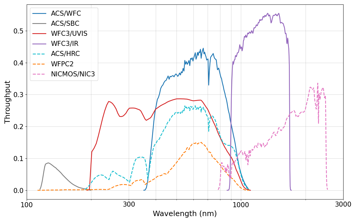
Figure 5.7 compares the wavelength-dependent throughputs of ACS/WFC and HRC with those of WFC3/UVIS, WFC3/IR, NICMOS/NIC3, and WFPC2.
5.2.3 Limiting Magnitudes
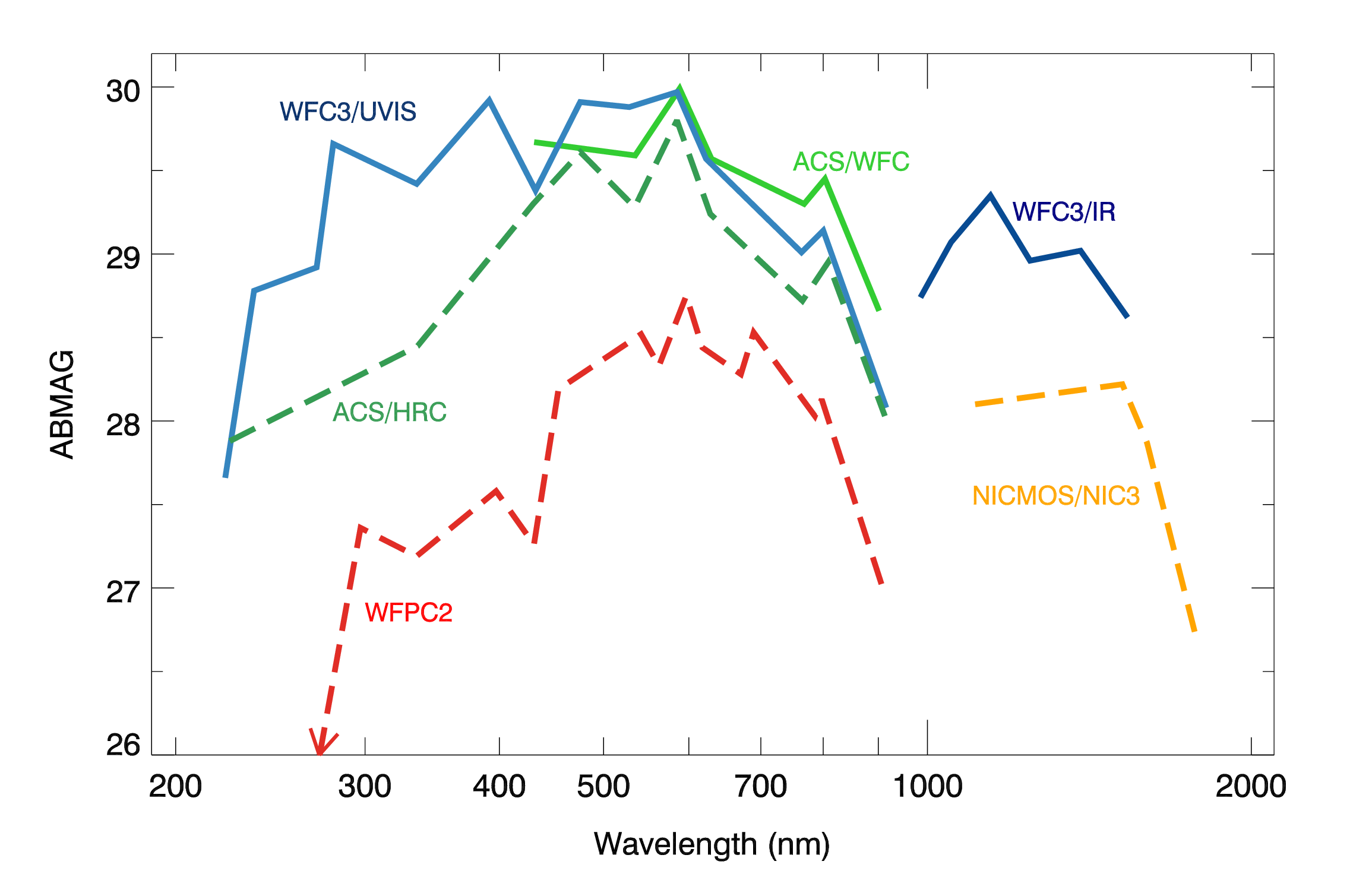
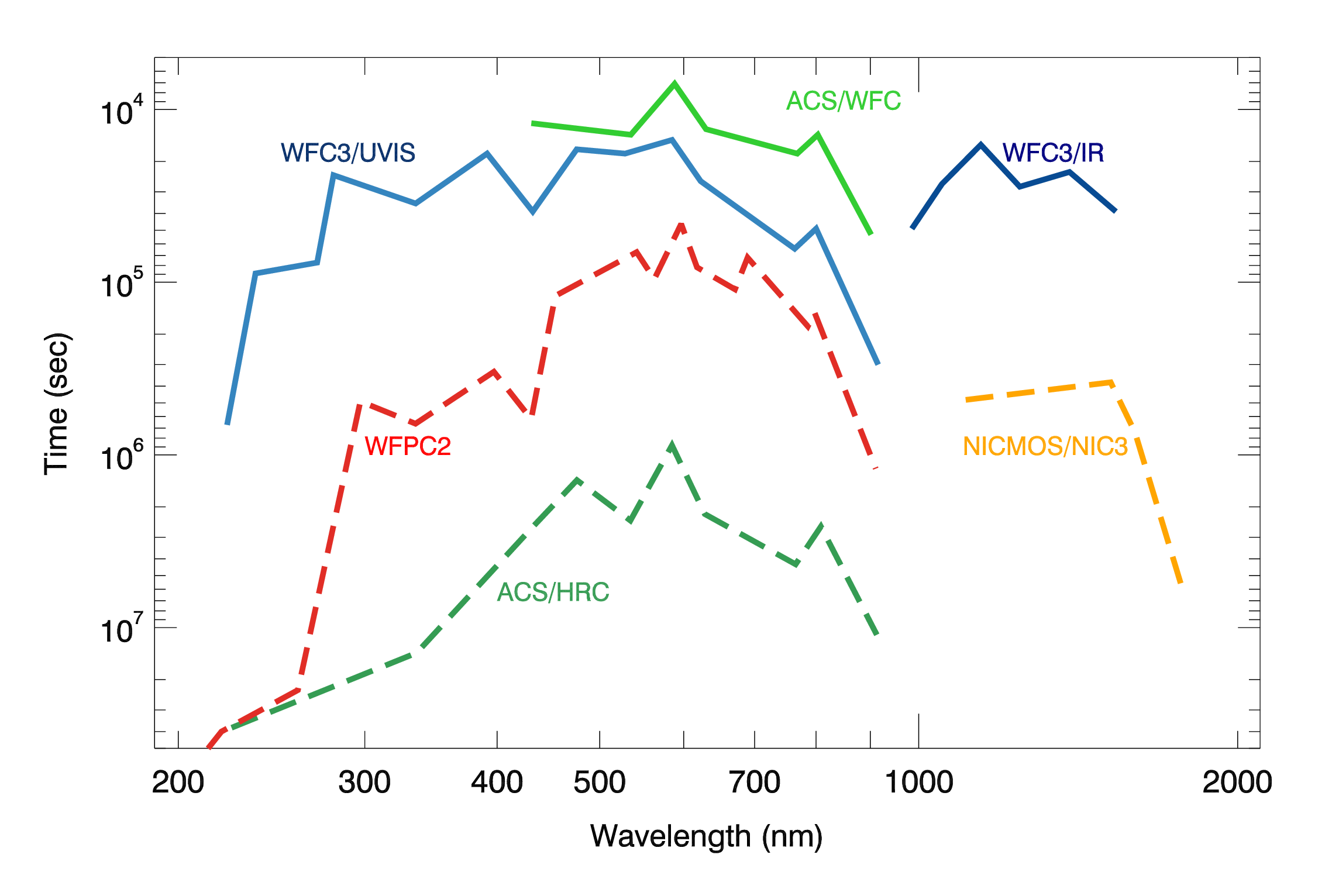
Table 5.4 contains the detection limits in Johnson-Cousins V magnitudes for unreddened O5V, A0V, and G2V stars, generated using the ETC. WFC and HRC values used the parameters # Frames=2, GAIN=2, and a 0.2 arcsecond circular aperture. For the SBC, a 0.5 arcsecond circular aperture was used. An average sky background was used in these examples. However, limiting magnitudes are sensitive to the background levels; for instance, the magnitude of an A0V in the WFC using the F606W filter changes by ±0.4 magnitudes at the background extremes. Figure 5.8 shows a comparison of the limiting magnitude for point sources achieved by the different cameras with a signal to noise of 5 in a 10 hour exposure. Figure 5.9 shows a comparison of the time needed for extended sources to attain ABMAG=26.
Table 5.4: V detection limits for ACS, HRC, and SBC direct imaging.
Camera | Filter | V limit (S/N = 5, exposure time = 1 hour) | ||
O5V (Kurucz model) | A0V (Vega) | G2V (Sun) | ||
WFC | F606W | 27.7 | 27.8 | 28.0 |
WFC | F814W | 26.6 | 27.0 | 27.7 |
HRC | F330W | 26.8 | 24.7 | 24.1 |
HRC | F606W | 27.3 | 27.3 | 27.5 |
SBC | F125LP | 27.6 | 23.0 | 14.0 |
5.2.4 Signal-To-Noise Ratios
Chapter 10 contains plots of exposure time versus magnitude for a desired signal-to-noise ratio. These plots are useful for estimating exposure times needed for your scientific objectives. More accurate estimates require the use of the ACS ETC.
5.2.5 Saturation
Both CCD and SBC imaging observations are subject to saturation at high total accumulated counts per pixel. For the CCDs, this is due either to the depth of the full well or to the 16 bit data format. See Section 4.3.1, ACS ISR 2019-03, and ACS ISR 2020-02 for more information on WFC saturation. For the SBC, this is due to the 16 bit format of the buffer memory (see Section 4.3.1 and Section 4.5.2). There are also health and safety considerations for the MAMA detector. See Section 4.6 for a discussion of bright object limits.
5.2.6 Faint Horizontal Striping in WFC CCDs
Subsequent to the replacement of the ACS CCD Electronics Box during SM4 in 2009, all WFC images show horizontal striping noise that is roughly constant across each row of readout in all four WFC amplifiers. This striping is the result of a 1/f noise on the bias reference voltage, and has an approximately Gaussian amplitude distribution with standard deviation of 0.9 electrons. The contribution of the stripes to the global read noise statistics is small, but the correlated nature of the noise may affect photometric precision for very faint sources and very low surface brightnesses (ACS ISR 2011-05).
During Cycle 17, an algorithm for removing the stripes from WFC science images was developed and tested. Because the WFC bias striping noise is highly consistent among the four readout amplifiers, and because it also manifests within the WFC prescan regions, a prescan-based de-striping algorithm was incorporated into the ACS calibration pipeline CALACS. This de-striping algorithm, as well as its implementation in CALACS, are described in Section 3.4 of the ACS Data Handbook. This permits consistent striping-noise mitigation for all post-SM4 WFC full-frame images, including calibration images. However, the de-striping algorithm is NOT automatically applied to subarray images within CALACS.
Post-SM4 WFC images can also be fully calibrated with a tool called acs_destripe_plus, which is available as part of the acstools package. This tool includes a stand-alone version of the de-striping algorithm that fits the stripes across the full science array, rather than fitting the stripes solely in the prescan columns. Within acs_destripe_plus, the destriping algorithm is run between the basic calibration tasks of ACSCCD and, if desired, the pixel-based CTE correction of ACSCTE. Post-SM4 WFC subarray images can only be de-striped and CTE-corrected using acs_destripe_plus. More details on processing WFC subarrays can be found in Section 7.3.1, ACS ISR 2017-06, and the ACS Subarrays notebook on the ACS Analysis Tools webpage.
Please see the acstools website for details on running acs_destripe_plus, as well as the example given in Section 3.5 of the ACS Data Handbook. Further details regarding the characterization, mitigation, and evolution of WFC bias striping noise are provided in ACS ISR 2011-05 and ACS ISR 2024-03.
-
ACS Instrument Handbook
- • Acknowledgments
- • Change Log
- • Chapter 1: Introduction
- Chapter 2: Considerations and Changes After SM4
- Chapter 3: ACS Capabilities, Design and Operations
- Chapter 4: Detector Performance
- Chapter 5: Imaging
- Chapter 6: Polarimetry, Coronagraphy, Prism and Grism Spectroscopy
-
Chapter 7: Observing Techniques
- • 7.1 Designing an ACS Observing Proposal
- • 7.2 SBC Bright Object Protection
- • 7.3 Operating Modes
- • 7.4 Patterns and Dithering
- • 7.5 A Road Map for Optimizing Observations
- • 7.6 CCD Gain Selection
- • 7.7 ACS Apertures
- • 7.8 Specifying Orientation on the Sky
- • 7.9 Parallel Observations
- • 7.10 Pointing Stability for Moving Targets
- Chapter 8: Overheads and Orbit-Time Determination
- Chapter 9: Exposure-Time Calculations
-
Chapter 10: Imaging Reference Material
- • 10.1 Introduction
- • 10.2 Using the Information in this Chapter
-
10.3 Throughputs and Correction Tables
- • WFC F435W
- • WFC F475W
- • WFC F502N
- • WFC F550M
- • WFC F555W
- • WFC F606W
- • WFC F625W
- • WFC F658N
- • WFC F660N
- • WFC F775W
- • WFC F814W
- • WFC F850LP
- • WFC G800L
- • WFC CLEAR
- • HRC F220W
- • HRC F250W
- • HRC F330W
- • HRC F344N
- • HRC F435W
- • HRC F475W
- • HRC F502N
- • HRC F550M
- • HRC F555W
- • HRC F606W
- • HRC F625W
- • HRC F658N
- • HRC F660N
- • HRC F775W
- • HRC F814W
- • HRC F850LP
- • HRC F892N
- • HRC G800L
- • HRC PR200L
- • HRC CLEAR
- • SBC F115LP
- • SBC F122M
- • SBC F125LP
- • SBC F140LP
- • SBC F150LP
- • SBC F165LP
- • SBC PR110L
- • SBC PR130L
- • 10.4 Geometric Distortion in ACS
- • Glossary


