7.7 ACS Apertures
HRC has been unavailable since January 2007. Information about the HRC is provided for archival purposes.
WFC may be offered as shared risk in Cycle 34 and receive minimal support and calibration. See the ACS website, Call for Proposals, and OPCR webpage for the latest status.
7.7.1 WFC Apertures
The active image area of each WFC detector is 4096 × 2048 pixel2. The mean plate scale is 0.05 arcseconds/pixel, and the combined detectors cover an approximately square area of 202 arcseconds on a side. In establishing reference pixel positions, we have to consider the physical prescans, which extend 24 pixels beyond the edges in the horizontal direction. Each CCD must therefore be regarded as a 4144 × 2048 pixel2 area. The gap between the two CCDs is equivalent to 50 pixels. In Figure 7.3, the letters A, B, C, and D show the corner locations of the four readout amplifiers.
We define apertures named WFC1 and WFC2, which represent the two CCDs, with their reference points near the geometric center of each chip at (2124, 1024). The positions have been moved about 50 pixels from the center line to avoid a discontinuity at the amplifier readout boundary. However, we keep two other apertures named WFC1-FIX and WFC2-FIX at the original central locations (2072,1024). For extended sources, choosing new positions may not be of any advantage and it may be more effective to use these fixed positions.
The aperture WFC encompasses both detectors, and has its reference point near the overall center but about 10 arcseconds away from the inter-CCD gap. This reference point is (2124, 200) on the WFC1 CCD. Again, this point has been moved away from the center line, but the reference point for WFC-FIX remains at (2072, 200). Selection of WFC1, WFC2, or WFC only changes the pixel where the target will be positioned. In all three cases, data is normally delivered in a file containing two science image extensions, one for each detector. See the ACS Data Handbook for details of the ACS data format. Reading out a subarray, which consists of part of only one of the CCDs, is done only if requested.
Figure 7.3: WFC full-frame aperture definitions.
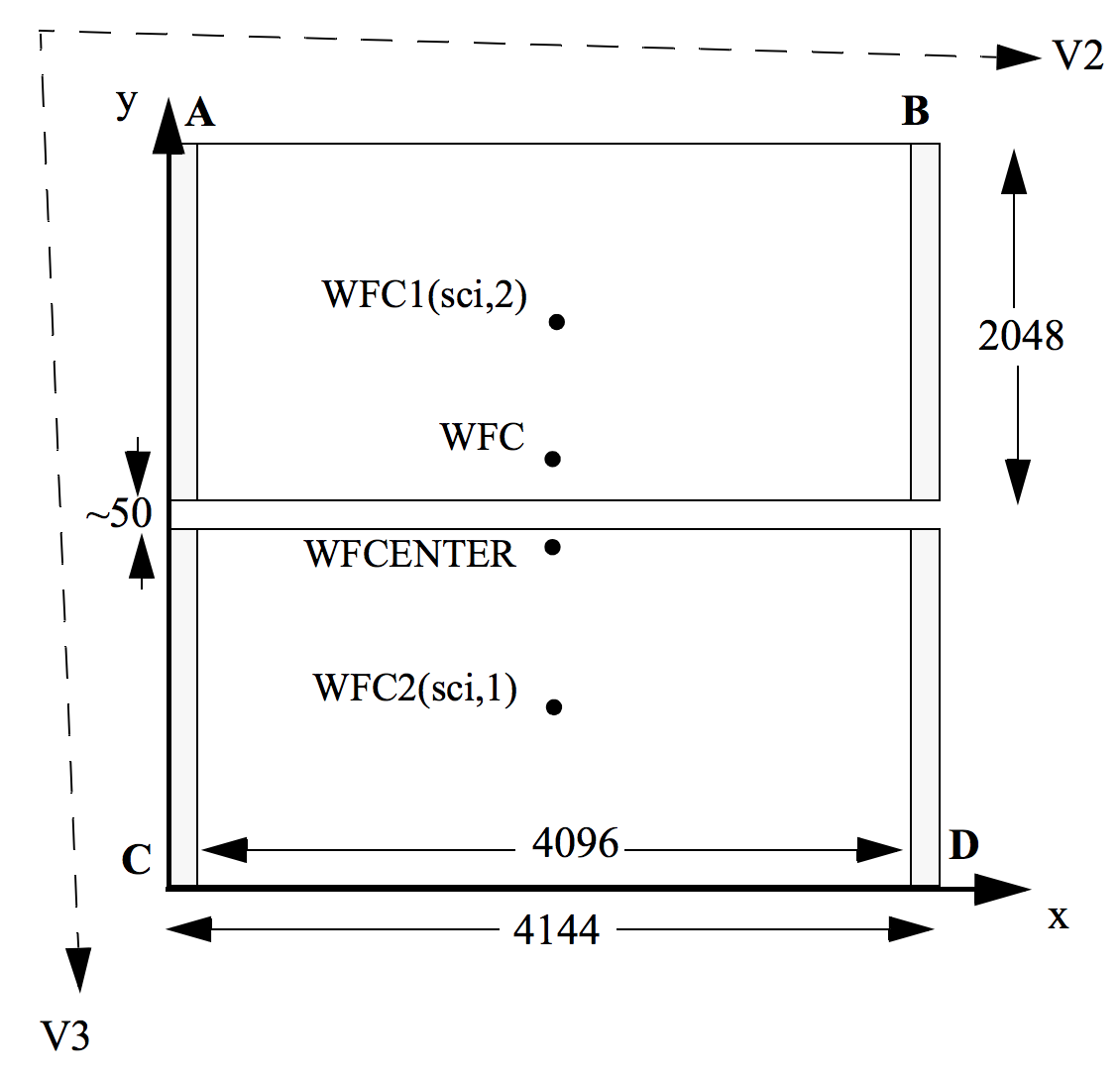
WFCENTER is similar to WFC, but is placed at the center of the combined WFC full field (2114.1, 2029.9). The center is defined as the average of the four corners in the distortion-corrected space. Because of the scale variation, this does not appear at the center in pixel space, but rather is on WFC2 about 20 pixels from the edge. Selection of WFCENTER can be of use in obtaining observations with maximum overlap at unique orientations and for mosaics.For sets of observations that take place over a substantial part of a year, the telescope roll limitations will require measurements to be taken over most of the angular range. On sky, the WFC aperture is roughly square, and it is natural to design observations in steps of 90° to consistently cover the same area. There will be some region at the edges not covered at all four orientations. However, a square area of side 194.8 arcseconds centered on WFCENTER, and with edges parallel to the V2 and V3 axes, is overlapped at all four positions. In designing a mosaic that combines observations at 90° steps, a translation of about 190 arcseconds between pointings would provide continuous coverage.
Figure 7.4: Schematic WFC apertures and ramp filters.
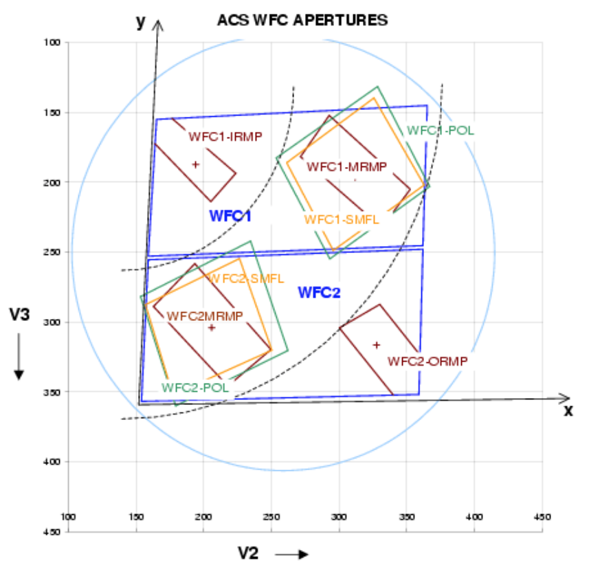
Shown are the approximate active areas defined by the filters. The actual readout areas are the quadrants for the polarizers and small (HRC) filters, and either the quadrant or the full chip for the ramp filters.
7.7.2 Ramp-Filter Apertures
WFC Ramp-Filter Apertures
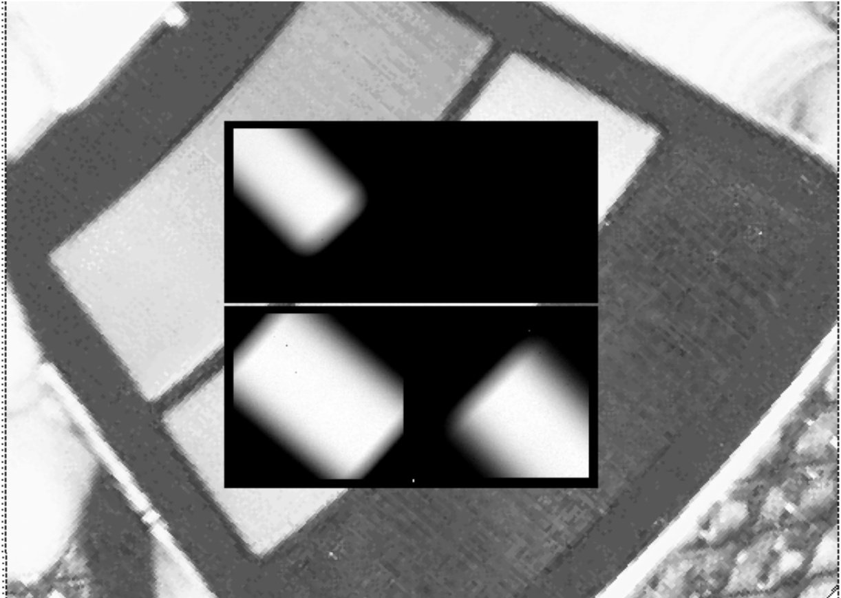
There are five ramp filters. Each ramp filter consists of three segments (inner, middle, outer) that can be rotated across the WFC field of view as indicated in Figure 7.4. The IRAMP filters can only be placed on WFC1 in a location that will define the aperture WFC1-IRAMP and the ORAMP filters only on WFC2 creating the aperture WFC2-ORAMP. The MRAMP filters can lie on WFC1 or WFC2 with corresponding apertures WFC1-MRAMP and WFC2-MRAMP. The approximate aperture locations are indicated in Figure 7.4, while actual data obtained during ground calibrations are overlaid on an image of a ramp filter in Figure 7.5. Operationally, a fixed reference point will be defined for each detector and filter combination. Then the ramp filter will be rotated to place the required wavelength at the reference position.
The reference positions for all defined apertures are given in Table 7.7 in pixels, and in the telescope (V2, V3) reference frame where values are measured in arc seconds. The values given here are based on in-flight calibration results. The x and y axis angles are measured in degrees from the V3 axis towards the V2 axis. This is in the same sense as measuring from North to East on the sky. The "extent" of the ramp filter apertures given in Table 7.7 are the FWHM of the monochromatic patches (visible in Figure 7.4) measured from a small sample of ground calibration data. To use a ramp filter in a Phase II program, specify the filter name, the central wavelength, and the aperture. The scheduling software will then automatically rotate the filter to the appropriate wavelength and point at the reference point of the aperture chosen.
The aperture chosen may either be the full CCD or just the quadrant on which the ramp filter lies. This second choice was new as of Cycle 15, and requires that the aperture be specified. The apertures matching each filter are given in Table 7.8. Those with names ending in Q are the quadrants. It will normally be preferable to choose the quadrant aperture to save data volume and buffer dumping time. All apertures may be used with non-ramp filters. A target may be put at the same position using a ramp and a non-ramp filter. Please see the footnotes to Table 7.7 for a complete list of available but unsupported apertures.
HRC Ramp Filter Apertures
Only the middle segments of the five ramp filters could be used with the HRC. They are FR914M, FR459M, FR505N, FR388N and FR656N. All five middle segments could be used with any of the HRC apertures listed in Table 7.8 (see Table 7.9 for the aperture reference positions). There were no special ramp apertures with the HRC because when a ramp filter is used with the HRC it covered the entire HRC CCD. This region was defined by the HRC aperture in Table 7.9. To use the HRC-512 or HRC-SUB1.8 subarray apertures with a ramp filter, POS TARGs had to be used to align the aperture correctly.
As with the WFC, the fixed reference point of the ramp aperture was defined operationally depending on the detector, aperture, and filter combination. Please refer to Section 7.3.1, Section 5.3.1, and ACS ISR 2002-01 for further information.
Figure 7.5: Monochromatic patches in ground calibration data showing actual aperture sizes through ramp filters (superimposed on photo of ramp filters).
7.7.3 The Small Filter Apertures
When a filter designed for the HRC is used with the WFC, it only covers a small area on either WFC1 or WFC2. The projected filter position can be placed on either chip by selection of the filter wheel setting. Figure 7.4 shows how the filter projection may be placed so as to avoid the borders of the CCDs. When a WFC observation is proposed using a HRC filter, spacecraft commanding software automatically uses internal built-in apertures designed for these observing scenarios, called WFC1-SMFL and WFC2-SMFL. Reference positions at or near the center of these apertures are defined so that a target may be placed in the region covered by the chosen filter. Note that WFC2-SMFL is available but not supported. Figure 5.11 shows the vignetted field of view produced by one of these filters, F892N, when used with WFC.
The axis angles given in Table 7.7 do not refer to the edges of the apertures as drawn, but rather to the orientation of the x and y axes at the WFC reference pixel. These angles vary slightly with position due to geometric distortion.
For the polarizers and F892N used with WFC, the default is to readout a subarray. The subarray is a rectangular area with sides parallel to the detector edges which encompasses the indicated filtered areas. For ramp filters, the default is to read out the entire WFC detector, unless a polarizer is used with the ramp filter, in which case a subarray is readout. Users cannot override the small filter subarrays.
Table 7.7: WFC aperture parameters.
APT Aperture Name | Readout area | Extent [a] | Reference | Reference | x-axis angle | y-axis angle |
|---|---|---|---|---|---|---|
WFC | 4096 × 4096 | 202 × 202 | (2124,200) | (262.41,238.91) | 92.163 | 177.552 |
WFC-FIX | 4096 × 4096 | 202 × 202 | (2072,200) on WFC1 | (259.84,239.01) | 92.178 | 177.532 |
WFCENTER | 4096 × 4096 | 202 × 202 | (2114.1,2029.9) on WFC2 | (261.53,252.30) | 92.056 | 177.527 |
WFC1 | 4096 × 4096 | 202 × 202 | (2124,1024) | (264.21,198.55) | 92.459 | 177.352 |
WFC1-FIX | 4096 × 4096 | 202 × 202 | (2072,1024) | (261.65,198.66) | 92.476 | 177.329 |
WFC2 | 4096 × 4096 | 202 × 202 | (2124,1024) | (259.97,302.48) | 91.700 | 177.780 |
WFC2-FIX | 4096 × 4096 | 202 × 202 | (2072,1024) | (257.37,302.56) | 91.710 | 177.765 |
WFC1-IRAMP | 4096 × 4096 | 25 × 65 | (680,1325) | (194.82,187.43) | 93.125 | 176.619 |
WFC1-MRAMP | 4096 × 4096 | 35 × 80 | (3096,1024) | (312.46,196.61) | 92.152 | 177.776 |
WFC2-MRAMP | 4096 × 4096 | 40 × 80 | (1048,1024) | (206.82,304.16) | 91.941 | 177.464 |
WFC2-ORAMP | 4096 × 4096 | 35 × 65 | (3494,708) | (328.52,316.63) | 91.363 | 178.237 |
WFC1-SMFL [b] | 2048 × 2048 | 70 × 80 | (3096,1024) | (312.46,196.61) | 92.152 | 177.776 |
2048 × 2048 | 70 × 80 | (1048,1024) | (206.82,304.16) | 91.941 | 177.464 | |
WFC1-POL0UV [d] | 2048 × 2048 | 90 × 80 | (3096,1024) | (312.46,196.61) | 92.142 | 177.761 |
WFC1-POL0V [d] | 2048 × 2048 | 90 × 80 | (3096,1024) | (312.46,196.61) | 92.156 | 177.783 |
2048 × 2048 | 90 × 80 | (1048,1024) | (206.82,304.16) | 91.925 | 177.444 | |
2048 × 2048 | 90 × 80 | (1048,1024) | (206.82,304.16) | 91.925 | 177.454 | |
WFC1A-2K | 2048 × 2048 | 101 × 101 | (1048,1024) | (211.69,200.98) | 92.845 | 176.890 |
WFC1B-2K | 2048 × 2048 | 101 × 101 | (3096,1024) | (312.46,196.61) | 92.152 | 177.776 |
WFC1A-1K | 2048 × 1024 | 101 × 50 | (1048,1536) | (213.07,176.39) | 93.059 | 176.708 |
WFC1B-1K | 2048 × 1024 | 101 × 50 | (3096,1536) | (313.45,171.72) | 92.303 | 177.670 |
WFC1A-512 | 2048 × 512 | 101 × 25 | (1048,1792) | (213.78,164.20) | 93.167 | 176.612 |
WFC1B-512 | 2048 × 512 | 101 × 25 | (3096,1792) | (313.96,159.38) | 92.380 | 177.614 |
WFC2C-2K | 2048 × 2048 | 101 × 101 | (1048,1024) | (206.82,304.16) | 91.941 | 177.464 |
WFC2D-2K | 2048 × 2048 | 101 × 101 | (3096,1024) | (308.82,301.11) | 91.518 | 178.068 |
WFC2C-1K | 2048 × 1024 | 101 × 50 | (1048,512) | (205.72,329.82) | 91.722 | 177.625 |
WFC2D-1K | 2048 × 1024 | 101 × 50 | (3096,512) | (307.96,327.09) | 91.368 | 178.161 |
WFC2C-512 | 2048 × 512 | 101 × 25 | (1048,256) | (205.19,343.72) | 91.612 | 177.705 |
WFC2D-512 | 2048 × 512 | 101 × 25 | (3096,256) | (307.55,340.14) | 91.293 | 178.207 |
WFC1-512 [c] | 512 × 512 | 25 × 25 | (3864,1792) | (352.33,157.88) | 92.106 | 177.969 |
WFC1-1K [c] | 1024 × 1024 | 50 × 50 | (3608,1536) | (339.04,170.73) | 92.130 | 177.903 |
WFC1-2K [c] | 2048 × 2046 | 101 × 101 | (3096,1024) | (312.46,196.61) | 92.152 | 177.776 |
WFC2-2K [c] | 2048 × 2046 | 101 × 101 | (1048,1024) | (206.82,304.16) | 91.941 | 177.464 |
WFC1-IRAMPQ | 2048 × 2046 | 25 × 65 | (680,1325) | (194.82,187.43) | 93.125 | 176.619 |
WFC1-MRAMPQ | 2048 × 2046 | 35 × 80 | (3096,1024) | (312.46,196.61) | 92.152 | 177.776 |
WFC2-MRAMPQ [c] | 2048 × 2046 | 40 × 80 | (1048,1024) | (206,304) | 91.9 | 177.5 |
WFC2-ORAMPQ | 2048 × 2046 | 35 × 65 | (3494,708) | (328.52,316.63) | 91.363 | 178.237 |
WFC1-CTE | 4096 × 4096 | 202 × 202 | (3920,1848) | (354.24,155.08) | 92.099 | 178.984 |
a Extent (arcsec) is the smaller of actual pixel domain readout and the area actively exposed to sky. For RAMP associated apertures the leading dimension is size yielding coverage at the specified wavelength.
b Apertures are automatically created by commanding software when an HRC filter is used in WFC observations. (Apertures are not listed in the APT aperture pull-down menu.)
c These are available but unsupported modes.
d Apertures are automatically created by commanding software when a polarizer filter is used. Same parameters apply for POL60 and POL120 in V and UV. (Apertures are not listed in the APT aperture pull-down menu.)
Table 7.8: Ramp filter apertures.
Detector | Filter | Ramp Segment | Full-frame apertures | Quadrant or |
|---|---|---|---|---|
WFC | FR423N | Inner | WFC1-IRAMP | WFC1-IRAMPQ |
WFC | FR388N | Middle | WFC1-MRAMP | WFC1-MRAMPQ |
WFC | FR462N | Outer | WFC2-ORAMP | WFC2-ORAMPQ |
HRC | FR914M | Middle | HRC | HRC-CORON1.8 |
7.7.4 Polarizer Apertures
Apertures have been provided for use with the polarizer sets similar to the SMFL apertures. These apertures are selected automatically when a polarizing spectral element is used, and a single WFC chip quadrant readout is obtained. The aperture parameters given in Table 7.7 are valid for all three polarizing filters in each polarizer set, UV or visible, to the stated significant figures.
7.7.5 HRC Apertures
The HRC had an area of 1062 × 1024 pixel2 including 19 physical overscan pixels at each end in the x direction. The active area was 1024 × 1024 pixel2. The mean scales along the x and y directions was 0.028 and 0.025 arcseconds/pixel, thus providing a field of view of about 29 × 26 arcsec2 in extent. The anisotropy and variation of scales is discussed in Section 10.4. The reference point for the aperture labelled HRC-FIX, and initially for HRC, was at the geometric center, (531, 512).
Figure 7.6: HRC coronagraphic finger and spots (left), coronagraphic finger always in data (right)
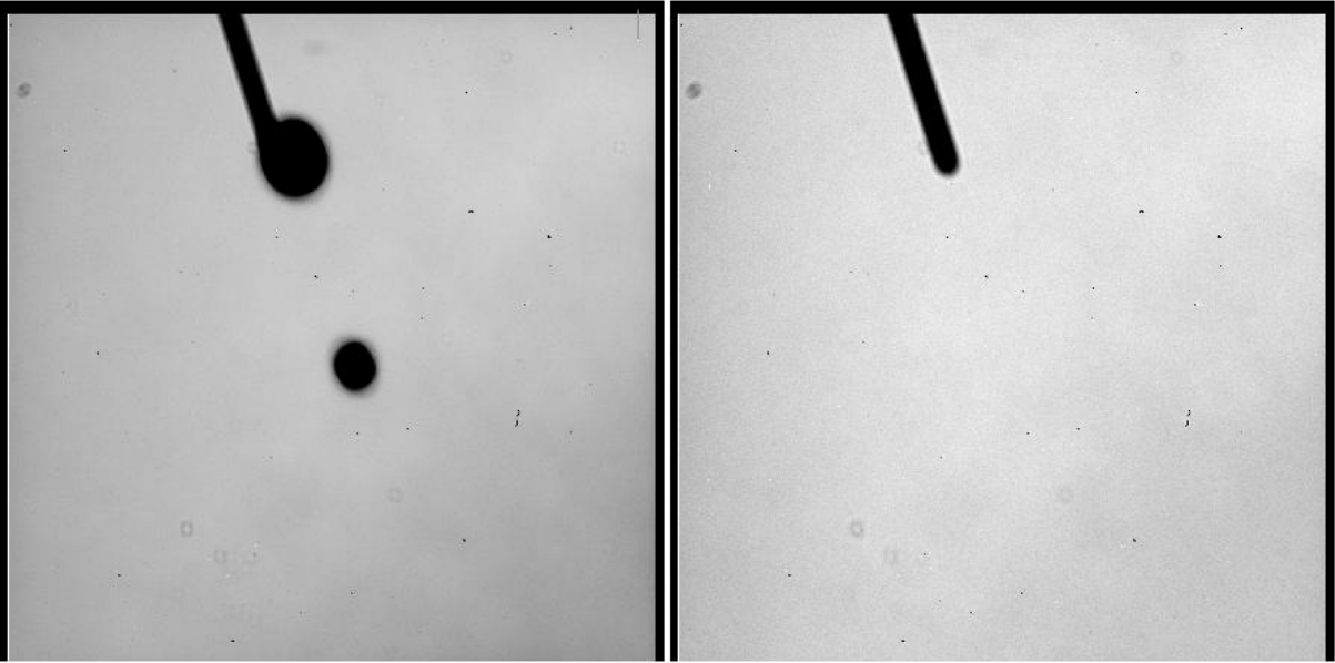
The HRC was equipped with two coronagraphic spots, nominally 1.8 and 3.0 arcseconds in diameter, and a coronagraphic finger, 0.8 arcseconds in width. Apertures HRC-CORON1.8, HRC-CORON3.0, and HRC-OCCULT0.8 were defined to correspond to these features. The coronagraphic spots were only in the optical train, and thus in the data, if HRC-CORON1.8 or HRC-CORON3.0 was specified. Their locations are shown in Figure 7.6 (left panel). In addition, we defined a target acquisition aperture, HRC-ACQ, designed for acquiring targets that were subsequently automatically placed behind a coronagraphic spot or the occultation finger. The positions of the coronagraphic spots were found to fluctuate and were tracked and updated over time via the SPOTTAB calibration file. Observations needed to incorporate a USE OFFSET Special Requirement to allow current values to be inserted at the time of the observation.
A substantial region masked out by the occulting finger was present in the HRC data (Figure 7.6, right panel). The occulting finger was not retractable. However, as with any other detector feature or artifact, the "lost" data could be recovered by combining exposures which were suitably shifted with respect to each other. A dither pattern, ACS-HRC-DITHER-LINE had been defined for this purpose and spanned the area flagged for the HRC occulting finger (~1.6 arcseconds or ~56 pixels wide), with an extra ~0.3 arcseconds or ~10 pixels of overlap.
Table 7.9: HRC aperture parameters.
APT Aperture Name | Active area | Extent | Reference | Reference V2,V3 | x-axis angle | y-axis angle |
|---|---|---|---|---|---|---|
HRC | 1024 × 1024 | 29 × 26 | (531,512) | (206,472) | –84.1 | 0.1 |
HRC-FIX | 1024 × 1024 | 29 × 26 | (531,512) | (206,472) | –84.1 | 0.1 |
HRC-CORON1.8 | 200 × 200 | 6 × 5 | (564,466) [a] | (205,471) [a] | –84.1 | 0.1 |
HRC-CORON3.0 | 200 × 200 | 6 × 5 | (467,794) [a] | (208,479) [a] | –84.2 | 0.1 |
HRC-OCCULT0.8 | 200 × 200 | 6 × 5 | (443,791) | (209,477) | –84.2 | 0.2 |
HRC-ACQ | 200 × 200 | 6 × 5 | (735,575) | (200,474) | –84.1 | 0.0 |
HRC-512 | 512 × 512 | 15 × 13 | (276,256) | (214,465) | –84.1 | 0.2 |
HRC-SUB1.8 | 512 × 512 | 15 × 13 | (570,468) | (205,471) | –84.1 | 0.1 |
HRC-PRISM [b] | 744 × 1024 | 21 × 26 | (671,512) | (214,471) | –84.2 | 0.2 |
a These values fluctuated and were updated via the SPOTTAB reference files appropriate for the time of observation.
b HRC-PRISM was automatically created by commanding software when spectral element PR200L and aperture HRC were selected in APT.
Use of the prism PR200L required specifying aperture HRC, but resulted in a reference point of (671, 512) to optimally center the target coordinates within the somewhat vignetted prism field of view. Although the HRC direct imaging and PR200L prism apertures had the same name in APT, they were actually distinct, and HST executed a small angle maneuver between observations of a given target with them, to compensate for the positional deflection by the prism. One consequence is that the Special Requirement SAME POS AS could not be used among mixed direct and prism exposures.
7.7.6 SBC Apertures
The SBC aperture is 1024 pixels square. There are no overscan pixels to consider. The x and y scales are 0.034 and 0.030 arcseconds/pixel leading to a coverage on the sky of 35 × 31 arcsec2. The reference point has been moved to (512, 400) to place targets further from a bad anode that disables several rows of the detector near y = 600. As with the CCDs we maintain an SBC-FIX aperture that will always have position (512, 512). MAMA detectors slowly lose efficiency with each exposure, therefore the SBC reference point may be shifted again if the chosen position exhibits significant loss of efficiency. The new aperture SBC-LODARK was enabled in October 2018. Near the reference pixel (175, 185) of this aperture, the dark rate of the detector remains at nominal level even at high temperatures. This aperture is therefore recommended when a visit will be longer than ~2 orbits and the target is small enough that it will not be affected by the elevated dark rates in the rest of the detector. See ACS ISR 2018-07 and ACS ISR 2024-04 for further details.
The (512, 512) reference point falls near to the same position in (V2, V3) as the HRC, namely (205, 470), and the x and y axis angles are −85.4° and −0.9°. Use of either prism PR110L or PR130L requires use of aperture SBC and results in a reference point of (425, 400) to optimally center the target coordinates with respect to vignetting on the right side of the field and to avoid a set of bad rows from 599 to 605.
Although the SBC direct imaging and prism apertures have the same name in APT, they are actually distinct, and HST executes a small angle maneuver between observations of a given target with them, to compensate for the positional deflection by the prisms. One consequence is that the Special Requirement SAME POS AS cannot be used among mixed direct and prism exposures. Figure 7.7 shows a direct and prism observation of the same field. The prism now is vignetted on the positive x side. The reference points and the small angle maneuver place the same target near the reference point of each view.
Table 7.10: SBC aperture parameters
APT Aperture | Active area | Extent | Reference | Reference | x-axis angle | y-axis angle |
|---|---|---|---|---|---|---|
SBC | 1024 × 1024 | 34 × 31 | (512, 400) | (205, 467) | –84.6 | –0.1 |
SBC-FIX | 1024 × 1024 | 34 × 31 | (512, 512) | (205, 470) | –84.6 | –0.1 |
SBC-PRISM [a] | 1024 × 1024 | 28 × 31 | (425, 400) | (203, 467) | –84.6 | –0.1 |
SBC-LODARK | 1024 × 1024 | 24 × 31 | (175, 185) | (217, 459) | -84.7 | 0.4 |
a SBC-PRISM is automatically created by commanding software when spectral elements PR110L and PR130L, and aperture SBC, are selected in APT.
Figure 7.7: Direct and prism observations of NGC6681.
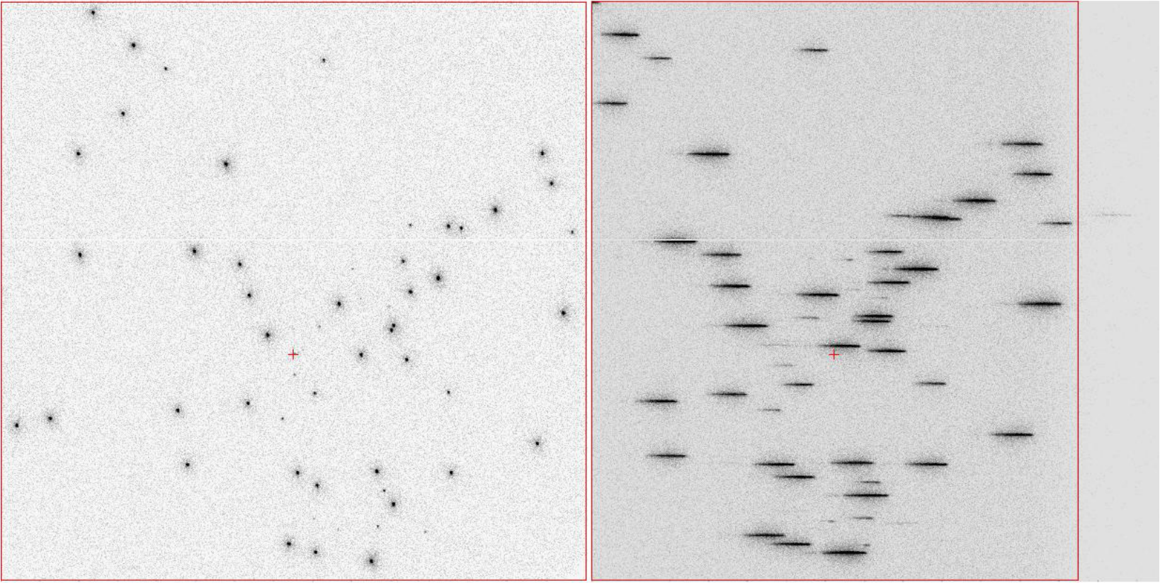
Direct and prism observations of NGC 6681. The reference point is defined to be at the center of each aperture in the x direction but below the center in the y direction to avoid the bad rows.
-
ACS Instrument Handbook
- • Acknowledgments
- • Change Log
- • Chapter 1: Introduction
- Chapter 2: Considerations and Changes After SM4
- Chapter 3: ACS Capabilities, Design and Operations
- Chapter 4: Detector Performance
- Chapter 5: Imaging
- Chapter 6: Polarimetry, Coronagraphy, Prism and Grism Spectroscopy
-
Chapter 7: Observing Techniques
- • 7.1 Designing an ACS Observing Proposal
- • 7.2 SBC Bright Object Protection
- • 7.3 Operating Modes
- • 7.4 Patterns and Dithering
- • 7.5 A Road Map for Optimizing Observations
- • 7.6 CCD Gain Selection
- • 7.7 ACS Apertures
- • 7.8 Specifying Orientation on the Sky
- • 7.9 Parallel Observations
- • 7.10 Pointing Stability for Moving Targets
- Chapter 8: Overheads and Orbit-Time Determination
- Chapter 9: Exposure-Time Calculations
-
Chapter 10: Imaging Reference Material
- • 10.1 Introduction
- • 10.2 Using the Information in this Chapter
-
10.3 Throughputs and Correction Tables
- • WFC F435W
- • WFC F475W
- • WFC F502N
- • WFC F550M
- • WFC F555W
- • WFC F606W
- • WFC F625W
- • WFC F658N
- • WFC F660N
- • WFC F775W
- • WFC F814W
- • WFC F850LP
- • WFC G800L
- • WFC CLEAR
- • HRC F220W
- • HRC F250W
- • HRC F330W
- • HRC F344N
- • HRC F435W
- • HRC F475W
- • HRC F502N
- • HRC F550M
- • HRC F555W
- • HRC F606W
- • HRC F625W
- • HRC F658N
- • HRC F660N
- • HRC F775W
- • HRC F814W
- • HRC F850LP
- • HRC F892N
- • HRC G800L
- • HRC PR200L
- • HRC CLEAR
- • SBC F115LP
- • SBC F122M
- • SBC F125LP
- • SBC F140LP
- • SBC F150LP
- • SBC F165LP
- • SBC PR110L
- • SBC PR130L
- • 10.4 Geometric Distortion in ACS
- • Glossary