5.5 Ultraviolet Imaging with the SBC
HRC has been unavailable since January 2007. Information about the HRC is provided for archival purposes.
The Solar Blind Channel is the ACS camera optimized for UV imaging. The SBC uses the same optical train as the HRC and is comparable in performance to the FUV MAMA of STIS. The use of the repeller wire increases the quantum efficiency of the detector by ~30%, but adds a halo to the PSF. Bright object limits are discussed in detail in Section 7.2.
5.5.1 Filter Set
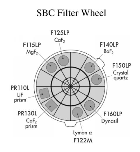
Several filters are available for use with the SBC, including a Lyman α narrow band filter (F122M), a long pass quartz filter (F150LP), MgF2 filter (F115LP), and a CaF2 filter (F125LP). The SBC also includes two additional long pass filters (F140LP and F165LP) as well as prisms (discussed in Section 6.3). Figure 5.12 shows the filter wheel used by SBC and Table 5.3 lists the filter characteristics in more detail.
5.5.2 Red Leaks
The visible light rejection of the SBC is excellent, but users should be aware that stars of solar type or later will have a significant fraction of the detected flux from outside the nominal wavelength range of the detector. This is discussed in greater detail in Section 4.4.2, and more information is available in Table 5.6. The stellar spectra are from the Pickles catalog (Pickles A.J., 1998, PASP 110, 863).
Table 5.6: Visible-light rejection of the SBC F115LP imaging mode.
Stellar | Percentage of all detected photons | Percentage of all detected photons |
|---|---|---|
O5V | 97.7 | 100 |
B1 V | 98.7 | 100 |
A0 V | 95.6 | 99.7 |
G0 V | 29.0 | 40.5 |
K0 V | 0. | 5.4 |
5.5.3 SBC Imaging Filter Shifts
The SBC focal surface, like that of the HRC, is tilted significantly with respect to the chief ray. The MAMA detector is a STIS spare, and as such, its window is approximately parallel to the Micro Channel Plate (MCP) surface and the whole detector must tilt to achieve good focus over the field. The window is therefore tilted, and to ameliorate the introduction of “lateral color”, which would result in dispersion-induced degradation of the PSF, the filters are canted in the opposite direction to that of the window. The filter thickness is matched to the mean index of refraction over its bandpass to maintain focus. These result in unavoidable image location offsets between filters. In contrast, the WFC and HRC filters and windows are normal to the chief ray and the detector surfaces are tilted within their housings to match the focal surface tilt. In Table 5.7, we list the shifts for each SBC imaging filter with respect to the F115LP filter. No pointing compensations are made for these offsets.
Table 5.7: Shifts between SBC imaging filters.
Spectral Element | Offset (pixels) in the x direction | Offset (pixels) in the y direction |
|---|---|---|
F115LP | 0 | 0 |
F122M | 0 | 0 |
F125LP | -5 | 15 |
F140LP | -7 | 21 |
F150LP | -3 | 11 |
F165LP | -4 | 12 |
-
ACS Instrument Handbook
- • Acknowledgments
- • Change Log
- • Chapter 1: Introduction
- Chapter 2: Considerations and Changes After SM4
- Chapter 3: ACS Capabilities, Design and Operations
- Chapter 4: Detector Performance
- Chapter 5: Imaging
- Chapter 6: Polarimetry, Coronagraphy, Prism and Grism Spectroscopy
-
Chapter 7: Observing Techniques
- • 7.1 Designing an ACS Observing Proposal
- • 7.2 SBC Bright Object Protection
- • 7.3 Operating Modes
- • 7.4 Patterns and Dithering
- • 7.5 A Road Map for Optimizing Observations
- • 7.6 CCD Gain Selection
- • 7.7 ACS Apertures
- • 7.8 Specifying Orientation on the Sky
- • 7.9 Parallel Observations
- • 7.10 Pointing Stability for Moving Targets
- Chapter 8: Overheads and Orbit-Time Determination
- Chapter 9: Exposure-Time Calculations
-
Chapter 10: Imaging Reference Material
- • 10.1 Introduction
- • 10.2 Using the Information in this Chapter
-
10.3 Throughputs and Correction Tables
- • WFC F435W
- • WFC F475W
- • WFC F502N
- • WFC F550M
- • WFC F555W
- • WFC F606W
- • WFC F625W
- • WFC F658N
- • WFC F660N
- • WFC F775W
- • WFC F814W
- • WFC F850LP
- • WFC G800L
- • WFC CLEAR
- • HRC F220W
- • HRC F250W
- • HRC F330W
- • HRC F344N
- • HRC F435W
- • HRC F475W
- • HRC F502N
- • HRC F550M
- • HRC F555W
- • HRC F606W
- • HRC F625W
- • HRC F658N
- • HRC F660N
- • HRC F775W
- • HRC F814W
- • HRC F850LP
- • HRC F892N
- • HRC G800L
- • HRC PR200L
- • HRC CLEAR
- • SBC F115LP
- • SBC F122M
- • SBC F125LP
- • SBC F140LP
- • SBC F150LP
- • SBC F165LP
- • SBC PR110L
- • SBC PR130L
- • 10.4 Geometric Distortion in ACS
- • Glossary
