6.1 Polarimetry
HRC has been unavailable since January 2007. Information about the HRC is provided for archival purposes.
WFC may be offered as shared risk in Cycle 34 and receive minimal support and calibration. See the ACS website, Call for Proposals, and OPCR webpage for the latest status.
6.1.1 Introduction
ACS offers two sets of polarizers, one optimized for near-UV/blue wavelengths (POLUV) and one optimized for visible/red wavelengths (POLV). Table 6.1 lists the filters that can be paired with the polarizers, as well as their availability (SUPPORTED, AVAILABLE but unsupported, or UNAVAILABLE). Note that none of the following filters can be used with the polarizers: F850LP, F892N, and all of the Linear Ramp Filters, because they reside in the same filter wheel as the polarizers. Regardless of the paired element, polarimetry requires that data be obtained in all three polarizers in order to measure the Stokes parameters.
As of Cycle 31, imaging spectropolarimetry is now supported, but is still being characterized and calibrated (more details can be found in Section 6.1.4 and Hathi et al., 2024, RNAAS 8, 56). Therefore, prior to proposing, potential observers should contact the HST Help Desk to discuss their specific goals and the current status of this mode.
Table 6.1: Filters and dispersing elements that can be used in conjunction with the ACS polarizers.
Polarizer set | Filters | Availability | Filter comments |
|---|---|---|---|
POL0UV | F220W | unavailable | HRC NUV short |
F250W | unavailable | HRC NUV long | |
F330W | unavailable | HRC U | |
F435W | available | Johnson B | |
F660N [a] | available | ||
F814W | available | Broad I | |
POL0V | F475W [a] | supported | SDSS g |
F502N | available | ||
F550M | available | ||
F555W | available | Johnson V | |
F606W [a] | supported | Johnson V Wide | |
F625W | available | SDSS r | |
F658N [a] | available | Hα | |
F775W [a] | supported | SDSS i | |
G800L | supported | Grism |
a These filters are part of an ACS program to calibrate the polarizer/filter combination to 1% or better
6.1.2 Performance of ACS Polarizers
At least three images through polarizers are required to determine the degree and position angle of polarization as well as the total intensity of the source. This is generally accomplished by observing the target through each of the three polarizers in the set. It can also be accomplished by obtaining observations at different spacecraft roll angles, but this drastically complicates the planning and transformation of the data into linear Stokes parameters.
Each set of ACS polarizers comprise three polarizing filters with relative position angles 0°, 60°, and 120°. The polarizers are aplanatic optical elements coated with Polacoat 105UV (POLUV set) and HN32 polaroid (POLV set). The POLUV set can be used throughout the visible region; it can be used for polarimetry over approximately 2000 Å to 8500 Å. However, the performance is severely degraded for wavelengths ≤ 3500 Å and ≥ 6500 Å. The POLV set is optimized for the visible region of the spectrum and is fully effective from 4500 Å to about 8000 Å.
The relative performance of the POLUV and POLV polarizers are shown in Figure 6.1. The POLV set provides superior perpendicular rejection in the 4500 Å to 8000 Å wavelength range, while the POLUV set delivers lower overall rejection across a wider range from 2000 Å to 7500 Å. Performance of the POLUV polarizers degrades at wavelengths longer than about 7500 Å, but useful observations may still be obtained up to approximately 8500 Å. In such cases, imperfect rejection of orthogonally polarized light must be considered during data analysis. Observers considering the use of the POLUV polarizers should consult with the HST Help Desk prior to submission of such a proposal.
Figure 6.1: Throughput and rejection of the ACS polarizers.
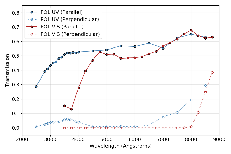
Parallel and perpendicular transmission as a function of wavelength for the POLUV and POLV polarizers.
| (1) | Q = \frac{2}{3}(2 im1 - im2 - im3) |
| (2) | U = \frac{2}{\sqrt 3}(im2 - im3) |
| (3) | I = \frac{2}{3}(im1 + im2 + im3) |
These parameters can be converted to the degree of polarization (P) and the polarization angle (θ) measured counterclockwise from the x axis as follows:
| (4) | P = \frac{\sqrt{Q^2 + U^2}}{I} |
| (5) | \theta = \frac{1}{2}\tan^{-1} (U/Q) |
A more detailed analysis, including allowances for imperfections in the polarizers, is given by Sparks & Axon 1999, PASP, 111, 1298, who found that the important parameter to consider for experiment design is the product of expected degree of polarization and signal-to-noise. For three ideal polarizers oriented at 60° relative position angles (as in ACS), the uncertainty in the degree of polarization P (which ranges from 0 for unpolarized light to 1 for fully polarized light) is approximately the inverse of the signal-to-noise per image. Specifically, Sparks & Axon found:
| (6) | \log{\left( \frac{\sigma_P}{P} \right)} = -0.102 - 0.9898\log{(P \left<\mathrm{S/N}\right>_i)} |
where σP is the uncertainty in the degree of polarization, and <S/N>i is the signal-to-noise of the ith image. The uncertainty in the polarization angle, σθ, is given by:
| (7) | \log{\sigma_{\theta}} = 1.514 - 1.068\log{(P\left<\mathrm{S/N}\right>_i)} |
This analysis pertains to ideal polarizers with no instrumental polarization. However, the ACS polarizers (especially the POLUV polarizers) allow significant leakage of cross-polarized light and the instrumental polarization of the WFC is ~2% (see ACS ISR 2004-09). The instrumental polarization of the HRC ranged from a minimum of 4% in the red to 14% in the far-UV. Other effects, such as phase retardance in the mirrors, may be significant as well. Please consult the STScI webpages for more detailed information, especially the ACS Data Handbook and ACS ISRs.
6.1.3 Implementation of ACS Polarizers
The ACS polarizers are easy to use. The observer selects a spectral element (filter or grism) and then obtains successive images with each of the three polarizers of the VIS set (POL0V, POL60V, POL120V) or the UV set (POL0UV, POL60UV, POL120UV). Once the spectral element and polarizer set are specified, the scheduling system automatically generates the slews that place the target in the optimal region of the field of view.
Because the POLUV and POLV sets are housed on separate filter wheels, the number of spectral elements available to each set is restricted. The available elements are determined by the relative performance of the polarizers and the near-UV limitations of the WFC caused by its silver mirror coatings. The POLUV set is mounted on Filter Wheel 1 and may be crossed with any filter mounted on Filter Wheel 2. The POLV set is mounted on Filter Wheel 2 and may be crossed with the G800L grism or any of the other associated filters in Table 6.1. GOs must plan their own calibration observations for those filters listed as AVAILABLE (but unsupported) in the table.
The polarizer sets were designed primarily for use with the HRC, where they offered a full unvignetted field of view (29 × 26 arcsec2) with any allowed imaging, spectroscopic, and coronagraphic combinations. When used with the WFC, the polarizers provide a vignetted, rectangular field of view that fits inside the WFC1B-2K subarray. Although this field of view is significantly smaller than the normal WFC field of view, it is approximately five times larger than that obtained with the HRC. To avoid the gap between the WFC CCDs and to optimize readout noise and CTE effects, the scheduling system will automatically slew the target to pixel (3096, 1024) on the WFC1 CCD whenever the WFC aperture and polarizer sets are selected. To reduce camera overhead times, a 2048 × 2048 subarray image centered on the target will be readout from WFC1 (Table 6.2).
Occasionally observers desire non-polarized images of targets at the same location on the detector as their polarized images. Doing so was straightforward with the HRC; one merely had to take an exposure without the polarizer in place. However, WFC polarimetry automatically invokes a large slew from the non-polarimetric imaging position. To obtain a non-polarized image at the same physical detector location as the polarized images, one must specify the WFC1B-2K aperture instead of the WFC aperture (Table 6.2).
Table 6.2: Examples of polarizer and non-polarizer exposures in a Phase II proposal. HRC apertures are no longer available but are shown for archival purposes.
Aperture | Filters | Comment |
|---|---|---|
HRC | F606W, POL0V | 1024 × 1024 image centered at usual HRC aperture. |
HRC | F606W, POL60V | Same but with POL60V. |
HRC | F606W, POL120V | Same but with POL120V. |
HRC | F606W | Non-polarizer image centered at same detector location as polarizer exposure. |
WFC | F606W, POL0V | Target automatically placed at WFC1 pixel (3096, 1024); 2048 × 2048 image. |
WFC | F606W, POL60V | Same but with POL60V. |
WFC | F606W, POL120V | Same but with POL120V. |
WFC1B-2K | F606W | Non-polarizer image at same detector location. Target at WFC1 pixel (3096, 1024); 2048 × 2048 image. |
6.1.4 Imaging Spectropolarimetry
The POLV polarizers can be paired with the G800L grism to obtain imaging spectropolarimetry with spectral resolving power (R~100 @ 8000Å) from ~4500Å – 8000Å. Even though the wavelength range of the G800L extends to 10500Å, the polarizing efficiency degrades rapidly for wavelengths ≥ 8000Å, rendering them completely ineffective at analyzing polarized light (Figure 6.1).
Commissioning and characterization of this mode in Cycle 30 indicates that this new mode will be capable of measuring polarization signals with precision in percentage polarization ~1-2%, and with similar absolute accuracy. Because this mode is slitless, it is most suited for point-sources. However, slightly extended sources up to 2-3 arcseconds have been observed as polarization calibrators during the commissioning process, and reliable results should still be obtained for such objects with intrinsic polarizations >~ 4-8%. Note that polarization follows a Rice as opposed to a Poisson distribution, so confident polarization measurements require an absolute minimum P/σp > 4; however, 5 is the highly recommended minimum. Spaxels may be binned to achieve this requirement, if necessary, but at the expense of spatial and spectral resolution.
As for all slitless grism observations, observers should take care in selecting a spacecraft orientation to eliminate (or at least minimize) contaminating spectra from nearby sources. In principle, observations taken at a different orientation from a first epoch can be used to disentangle the contamination, but polarimetry is very sensitive to flux mismatches, and such a procedure has not been evaluated for spectropolarimetry. Therefore, prior to proposing, potential observers should contact the HST Help Desk to discuss their specific goals and the current status of this mode.
6.1.5 Challenges and Limitations of ACS Polarimetry
The most accurate ACS polarimetry was obtained in the visible bands (i.e., F606W) with the POLUV and POLV polarizers, but we do not recommend using the POLUV polarizers due to their lower polarizing efficiencies. This mode had the advantage of very high rejection of perpendicular polarization and known mirror coatings with readily modeled properties. Because the WFC mirror coatings are proprietary, models of their polarization properties (e.g., the phase retardance of the IM3 mirror) are unavailable. Consequently, calibrating WFC polarized images is much more difficult than calibrating the HRC images. The ACS Team has an ongoing campaign to photometrically calibrate WFC polarimetry with both sets of polarizers. Data has been obtained that should provide improved calibration for the following filters, in combination with the appropriate set of polarizers: F435W, F475W, F606W, and F775W. We encourage users to periodically check the ACS webpage and published ISRs for any updates. Observers should contact the HST Help Desk to discuss their specific science goals prior to proposal submission.
UV polarimetry with ACS is challenging because the POLUV polarizers have relatively poor orthogonal rejection. In addition, while the instrumental polarization of the HRC was 4% to 7% in the visible, it rose to 8% to 9% in the UV and reached 14% at 2200 Å (see ACS ISR 2004-09). Far-UV polarimetry is especially challenging because the POLUV properties are not well-characterized shortwards of 2800 Å, and they appear to change rapidly with wavelength. Moreover, the low UV transmission of the POLUV polarizers and the poor rejection in the far-red exacerbate the red leaks seen in the far-UV spectral filters. Because the HRC is no longer available, the POLUV polarizers can only be used with the WFC, and the POLV filters will deliver superior performance.
The ACS team recently examined the impact of the pixel-based CTE correction algorithm on the ability to accurately measure polarization in ACS observations (see ACS ISR 2021-01). The investigation used simulated observations of point sources with different fractional polarizations, source brightnesses, and background levels. It found that the pixel-based CTE-corrected images induced ~0.1% additional polarization signal for 100% polarized sources farthest from the serial register, and that the induced signal decreases with decreasing polarization. Overall, this induced polarization effect is negligible compared to other sources of polarization uncertainty, therefore the net effect of CTE loss on ACS polarimetry is minimal.
The polarizers contribute a weak geometric distortion that rises to about 0.3 pixels near the edges of the HRC field of view. This distortion is caused by a weak positive lens in the polarizers that is needed to maintain proper focus when multiple filters are in the beam. The POLV polarizers also have a weak ripple structure intrinsic to their polaroid coatings. These ripples contribute an additional ±0.3 pixel distortion with a very complex structure (see ACS ISR 2004-10 and ACS ISR 2004-11). All these geometric effects are correctable with the AstroDrizzle software. However, astrometry will be less accurate with the polarizers because of residual errors and imperfect corrections.
Finally, the POL0V and POL60V filters contain bubbles which impact the PSF and flat fields. These bubbles are far out of focus and appear as large concentric bright and dark rings (400 pixels diameter in WFC, 370 pixels in HRC) and streaks in the flat fields. The worst case appeared in HRC POL60V images, where the amplitude of the artifacts reaches ±4% in the flats and the affected region was roughly centered at pixel (x, y) = (835, 430). Polarimetric combinations involving POL0V or the WFC are relatively minor, with typical amplitudes of ±1%. Observers requiring precision polarimetry should avoid these regions of the field of view. Although the polarizer flats attempt to correct these features (see ACS ISR 2005-10), the corrections are imperfect and dependent on the brightness and angular size of the target. The locations of these features and their effects can be discerned more accurately by examining the P-flats for the respective spectral filter crossed with the visual polarizers.
-
ACS Instrument Handbook
- • Acknowledgments
- • Change Log
- • Chapter 1: Introduction
- Chapter 2: Considerations and Changes After SM4
- Chapter 3: ACS Capabilities, Design and Operations
- Chapter 4: Detector Performance
- Chapter 5: Imaging
- Chapter 6: Polarimetry, Coronagraphy, Prism and Grism Spectroscopy
-
Chapter 7: Observing Techniques
- • 7.1 Designing an ACS Observing Proposal
- • 7.2 SBC Bright Object Protection
- • 7.3 Operating Modes
- • 7.4 Patterns and Dithering
- • 7.5 A Road Map for Optimizing Observations
- • 7.6 CCD Gain Selection
- • 7.7 ACS Apertures
- • 7.8 Specifying Orientation on the Sky
- • 7.9 Parallel Observations
- • 7.10 Pointing Stability for Moving Targets
- Chapter 8: Overheads and Orbit-Time Determination
- Chapter 9: Exposure-Time Calculations
-
Chapter 10: Imaging Reference Material
- • 10.1 Introduction
- • 10.2 Using the Information in this Chapter
-
10.3 Throughputs and Correction Tables
- • WFC F435W
- • WFC F475W
- • WFC F502N
- • WFC F550M
- • WFC F555W
- • WFC F606W
- • WFC F625W
- • WFC F658N
- • WFC F660N
- • WFC F775W
- • WFC F814W
- • WFC F850LP
- • WFC G800L
- • WFC CLEAR
- • HRC F220W
- • HRC F250W
- • HRC F330W
- • HRC F344N
- • HRC F435W
- • HRC F475W
- • HRC F502N
- • HRC F550M
- • HRC F555W
- • HRC F606W
- • HRC F625W
- • HRC F658N
- • HRC F660N
- • HRC F775W
- • HRC F814W
- • HRC F850LP
- • HRC F892N
- • HRC G800L
- • HRC PR200L
- • HRC CLEAR
- • SBC F115LP
- • SBC F122M
- • SBC F125LP
- • SBC F140LP
- • SBC F150LP
- • SBC F165LP
- • SBC PR110L
- • SBC PR130L
- • 10.4 Geometric Distortion in ACS
- • Glossary