4.5 SBC Operations and Limitations
4.5.1 SBC Scheduling Policies
The SBC MAMA is a STIS spare. The STIS MAMA control electronics are subject to resets due to cosmic-ray upsets. Therefore, STIS MAMAs are operated only during the contiguous orbits of each day that are free of the South Atlantic Anomaly (SAA). Even though the design of the ACS MAMA control electronics in the SBC was modified so that they would not be susceptible to cosmic-ray hits, the background count rate still exceeds the bright object limits for the SBC during SAA passage. Consequently, the SBC will only be scheduled for use during SAA-free orbits.
4.5.2 MAMA Overflow of the 16 Bit Buffer
The MAMA is a photon-counting detector: as each event is recorded, the buffer memory for the corresponding pixel is incremented by one integer. The buffer memory stores values as 16 bit integers; hence, the maximum number it can accommodate is 65,535 counts per pixel in a given ACCUM mode observation. When accumulated counts per pixel exceed this number, the values will wrap, i.e., the memory resets to zero. As an example, if you are counting at 25 counts/second/pixel, you will reach the MAMA "accumulation" limit in ~44 minutes.
The accumulated counts per pixel can be kept below this value by breaking individual exposures into multiple identical exposures, each of which is short enough that fewer than 65,535 counts are accumulated per pixel. There is no read noise for MAMA observations, so no penalty is paid in lost signal-to-noise ratio when exposures are split. There is only a small overhead for each MAMA exposure (see Section 8.2).
Keep the accumulated counts per SBC pixel below 65,535 by breaking single exposures into multiple exposures, as needed.
4.5.3 MAMA Darks
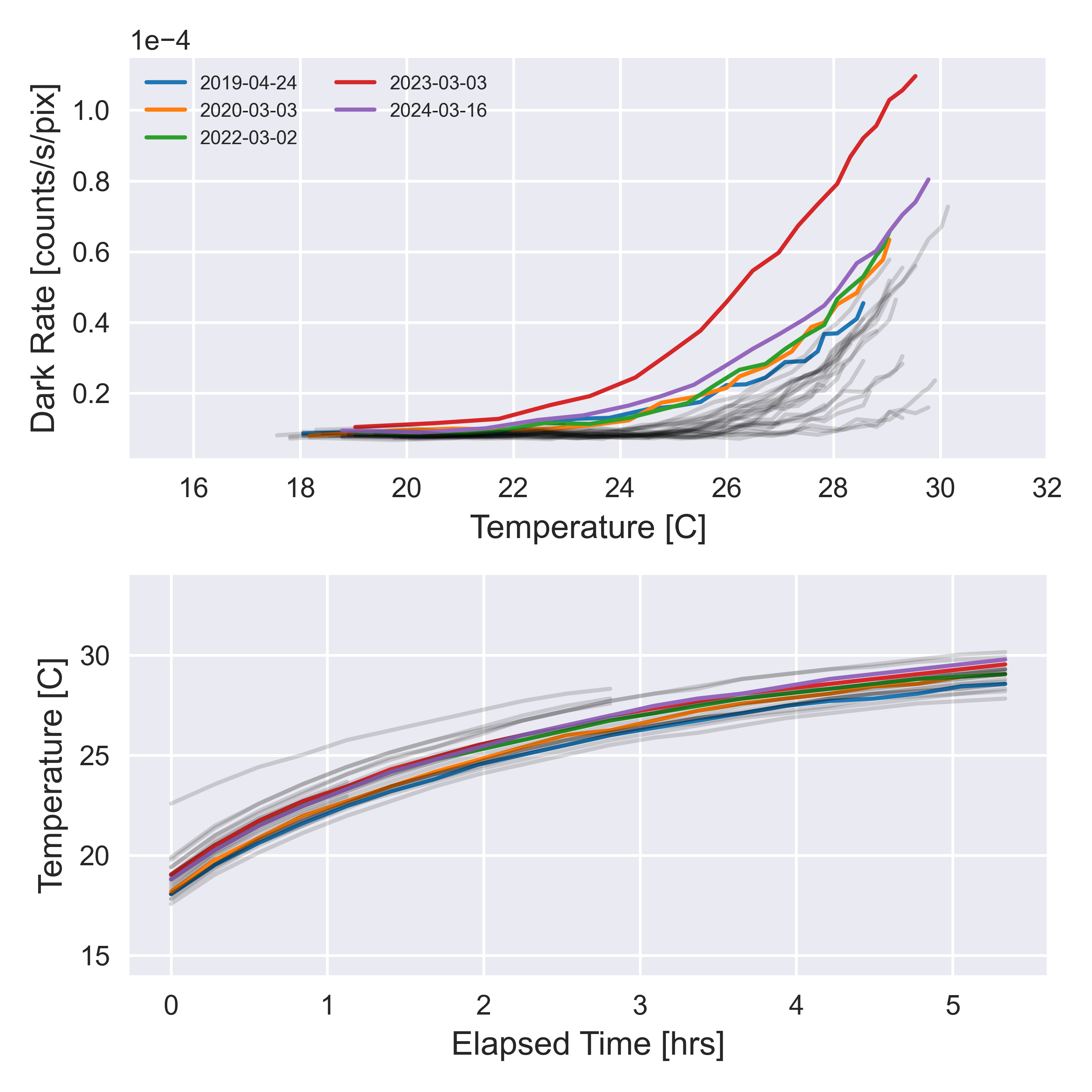
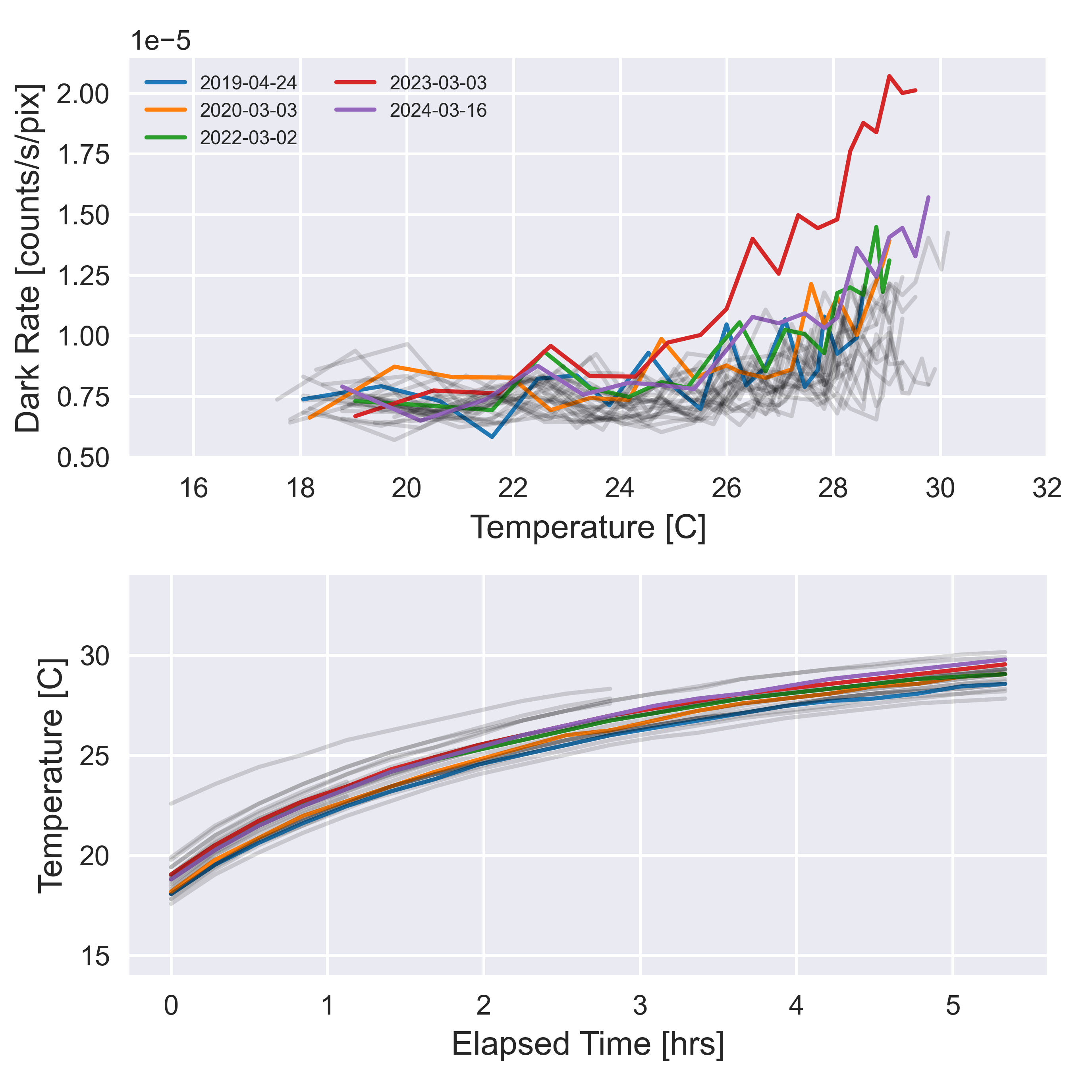
MAMA detectors have intrinsically low dark currents. Ground test measurements of the ACS MAMA showed count rates in the range 10–5 to 10–4 counts/s/pixel as the temperature varied from 28°C to 35°C. The count rate increases by about 30% for one degree increase in temperature. A recent study of in-flight data investigated how the temperature impacts the dark rate when the detector is left on for a long period of time (ACS ISR 2017-04). The dark rate remains as stable as ever. It is 8.52 × 10⁻⁶ counts/s/pixel while the instrument is below ~25°C (Figure 4.16). Above that temperature, the central region of the detector begins to experience an increasingly higher dark rate (Figure 4.17). That being the case, dark frames cannot be subtracted from science observations like they are with CCDs. Unlike CCDs, MAMA dark images are not meant to capture hot and warm pixels. Instead, dark rate in MAMA detectors shows up as random background noise. For the purposes of scientific analysis, the dark rate can be subtracted along with the background, at least when the detector is still below ~25°C. Above that temperature, users should still be able to do a local subtraction, but should be aware of the pattern present in the dark rate. Alternatively, observers can use the SBC-LODARK aperture if they plan to use the SBC for visits longer than two orbits and the target is small (see Section 7.7.6). Even during visits when the overall detector’s dark rate is elevated, the SBC-LODARK aperture consistently maintains low levels of dark current (Figure 4.16, Figure 4.17; ACS ISR 2024-04)
4.5.4 SBC Signal-To-Noise Ratio Limitations
MAMA detectors are capable of delivering signal-to-noise ratios of order 100:1 per resolution element (2 × 2 pixels) or even higher. On-orbit tests have demonstrated that such high S/N is possible with STIS (Kaiser et al., 1998, PASP, 110, 978; STIS ISR 1998-16). For targets observed at a fixed position on the detector, the signal-to-noise ratio is limited by systematic uncertainties in the small-scale spatial and spectral response of the detector. The MAMA flats show a fixed pattern that is a combination of several effects including beating between the MCP array and the anode pixel array, variations in the charge-cloud structure at the anode, and low-level capacitive cross-coupling between the fine anode elements. Intrinsic pixel-to-pixel variations are of order 4% but are stable to < 1%. Photometric accuracy can be improved by averaging over flat-field errors by dithering the observation (see Section 7.4).
4.5.5 SBC Flat field
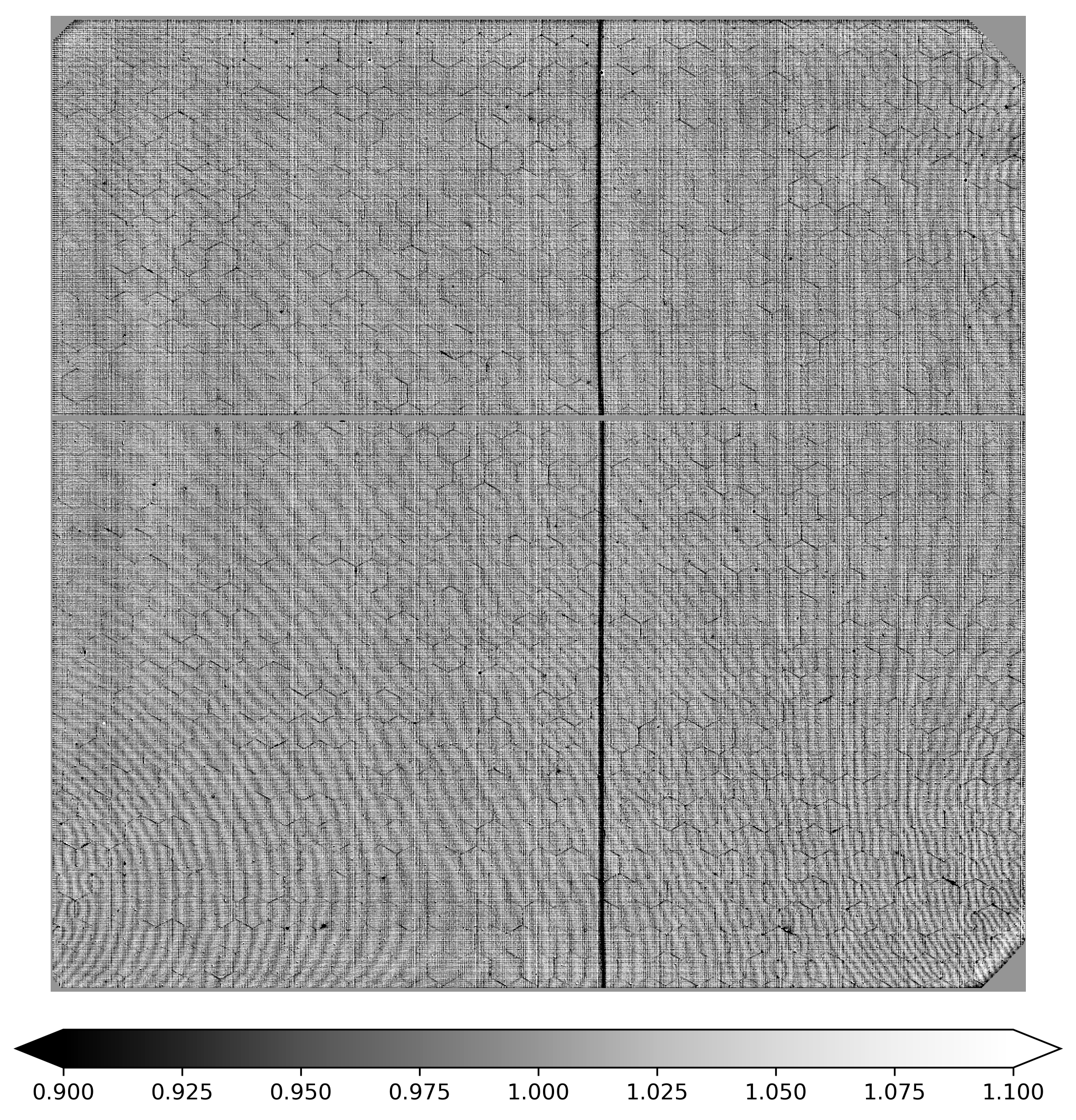
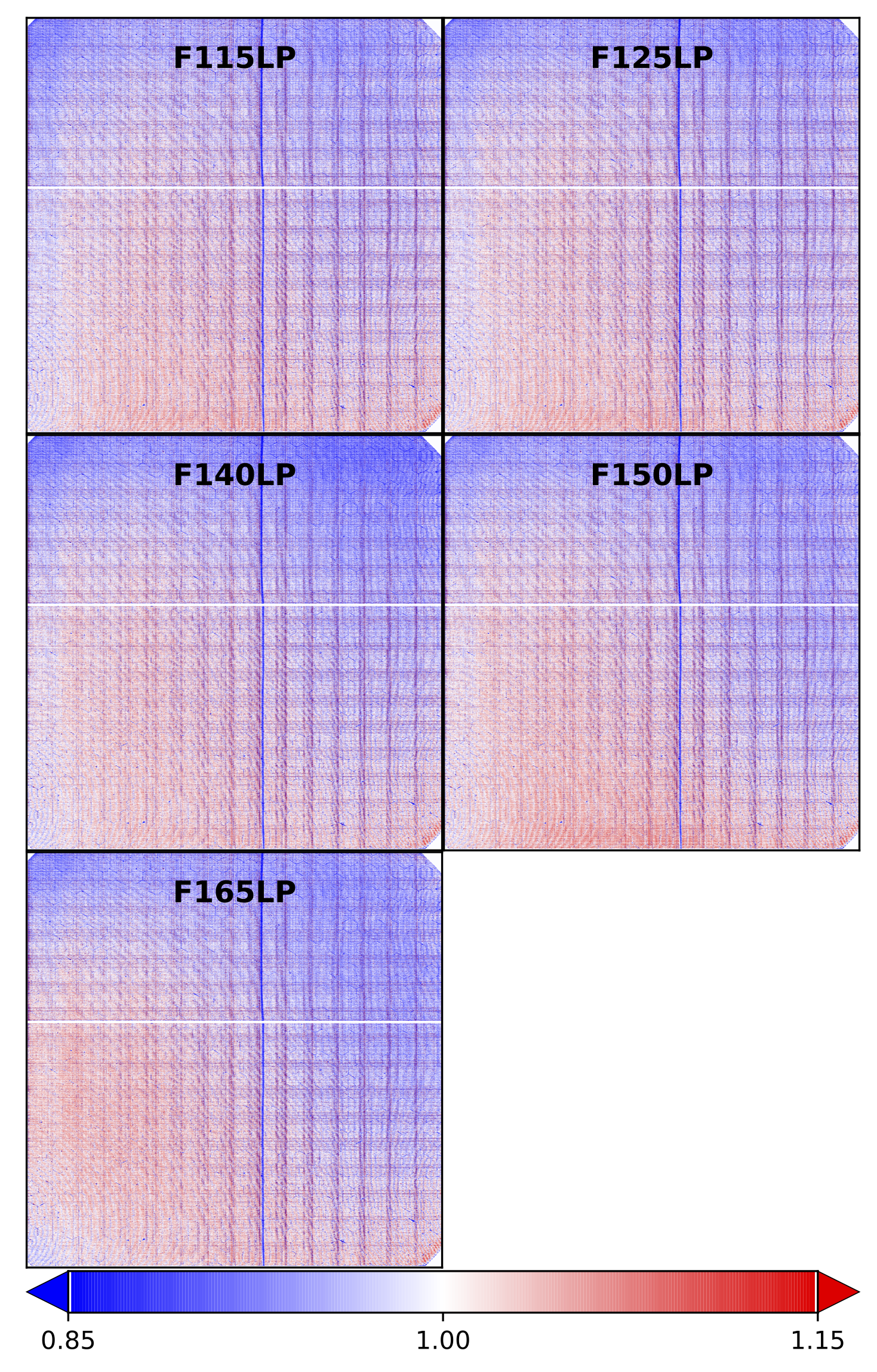
36h2201nj_pfl.fits) for the SBC MAMA (full frame shown).p5p1513pj_pfl.fits, and images taken after that date use 36h2201nj_pfl.fits. The P-flat in Figure 4.18 shows the effect of the disabled broken anode for rows 600 to 605 and of the shadow of the repeller wire around column 577.The L-flats are combined with the two sets of P-flats to make the final LP-flats. In June 2019, a set of ten LP-flats were delivered to the Calibration Reference Data System (CRDS) for use in the calibration pipeline. SBC images in MAST have been re-processed using these new LP-flats. Figure 4.19 shows five of the the imaging mode LP-flats used for new observations.
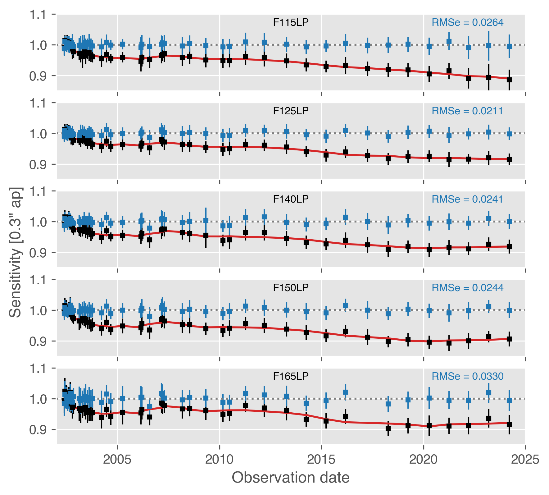
4.5.6 SBC Sensitivity
PHOTFLAM header keyword in SBC images is populated with the correct value. The default behavior of pysynphot and stsynphot when performing simulations of imaging modes is to assume a sensitivity corresponding to the middle of the upcoming cycle. The ETC assumes the same date. Users should consult the ETC release notes to identify the exact date being used.
4.5.7 SBC Linearity
Global
The MAMA detector maintains linearity (i.e., photon impact rate is linearly proportional to detected count rate) at globally integrated count rates up to 200,000 counts/second. At global rates exceeding 285,000 counts/second, both the MAMA detector and processing software are unable to reliably count photons. For these reasons, and to protect the MAMA from over-illumination, observations yielding global count rates above 200,000 counts/second are not allowed (see Section 4.6).
Local
The MAMA pixels are linear to better than 1% up to ~22 counts/second/pixel. Linearity at higher count rates is image-dependent such that the linearity of one pixel depends on the photon rate affecting neighboring pixels. Consequently, it is impossible to reliably correct for local deviations from linearity in post-observation data processing. MAMA detectors are also subject to damage at high local count rates, so observations yielding local count rates above 50 counts/second/pixel are not allowed (see Section 4.6).
-
ACS Instrument Handbook
- • Acknowledgments
- • Change Log
- • Chapter 1: Introduction
- Chapter 2: Considerations and Changes After SM4
- Chapter 3: ACS Capabilities, Design and Operations
- Chapter 4: Detector Performance
- Chapter 5: Imaging
- Chapter 6: Polarimetry, Coronagraphy, Prism and Grism Spectroscopy
-
Chapter 7: Observing Techniques
- • 7.1 Designing an ACS Observing Proposal
- • 7.2 SBC Bright Object Protection
- • 7.3 Operating Modes
- • 7.4 Patterns and Dithering
- • 7.5 A Road Map for Optimizing Observations
- • 7.6 CCD Gain Selection
- • 7.7 ACS Apertures
- • 7.8 Specifying Orientation on the Sky
- • 7.9 Parallel Observations
- • 7.10 Pointing Stability for Moving Targets
- Chapter 8: Overheads and Orbit-Time Determination
- Chapter 9: Exposure-Time Calculations
-
Chapter 10: Imaging Reference Material
- • 10.1 Introduction
- • 10.2 Using the Information in this Chapter
-
10.3 Throughputs and Correction Tables
- • WFC F435W
- • WFC F475W
- • WFC F502N
- • WFC F550M
- • WFC F555W
- • WFC F606W
- • WFC F625W
- • WFC F658N
- • WFC F660N
- • WFC F775W
- • WFC F814W
- • WFC F850LP
- • WFC G800L
- • WFC CLEAR
- • HRC F220W
- • HRC F250W
- • HRC F330W
- • HRC F344N
- • HRC F435W
- • HRC F475W
- • HRC F502N
- • HRC F550M
- • HRC F555W
- • HRC F606W
- • HRC F625W
- • HRC F658N
- • HRC F660N
- • HRC F775W
- • HRC F814W
- • HRC F850LP
- • HRC F892N
- • HRC G800L
- • HRC PR200L
- • HRC CLEAR
- • SBC F115LP
- • SBC F122M
- • SBC F125LP
- • SBC F140LP
- • SBC F150LP
- • SBC F165LP
- • SBC PR110L
- • SBC PR130L
- • 10.4 Geometric Distortion in ACS
- • Glossary
