11.4 Fixing Orientation on the Sky
STIS users, particularly those using the long slits to observe extended sources, commonly wish to specify the orientation of the slit on the sky. Specific orientations may also be used to place multiple point sources in a long slit (to be observed simultaneously) or to make sure that overly bright nearby stars are excluded. Observers planning coordinated parallel observations may also wish to specify the orientation of the HST focal plane, so as to place the appropriate instrument to cover a given patch of sky. Setting the orientation of the telescope means to effectively constrain the times when the observations can be scheduled, since HST must maintain a spacecraft orientation (sometimes called roll angle) which keeps its solar panels roughly perpendicular to the incoming sunlight. A roll ranges report, available in the APT Visit Planner, shows the range(s) of roll angle possible for a given observation as a function of observation date.
The orientation of the spacecraft (and therefore of the STIS long slits which are fixed in relation to the HST focal plane) is controlled by the ORIENT special requirement, which is entered during Phase II. The Phase II Proposal Instructions contain a detailed description of orientations and how to specify them. A specific orientation can be set, or a range of allowed orientations (e.g., 90–110 degrees) can be given. The tighter the constraints, the more difficult it will be to schedule the observation.
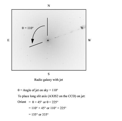
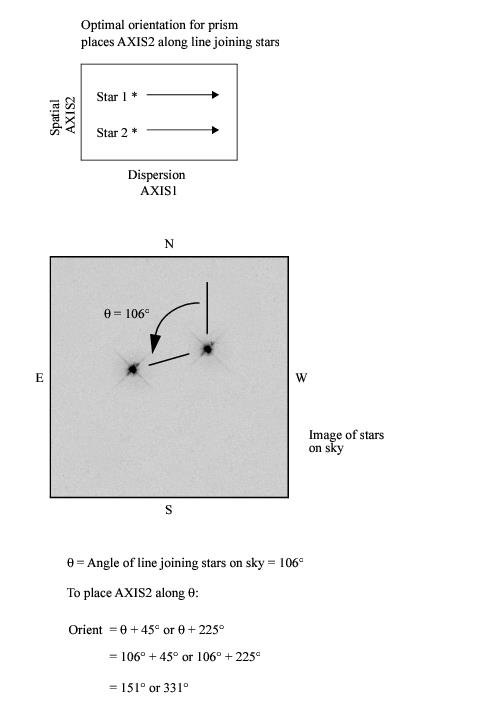
The ORIENT parameter gives the orientation of the HST focal plane projected onto the sky and is defined by the U2 and U3 axes. Figure 3.2 shows the HST focal plane containing all the HST instruments, with the U2 and U3 axes defined. Figure 11.1 shows the relationship between these axes and the position angle (PA) of the STIS long slits on the sky. Note that the long slits are approximately aligned with the detector's AXIS2, i.e., they are directly perpendicular to the dispersion axis (AXIS1). The important point to note is that if you fix the orientation of a long slit on the sky to be PA = Χ, where Χ is measured in degrees east of north, then the ORIENT parameter (which determines where the other HST instruments lie for parallel observations) is given as Χ+45 or Χ+225 degrees. Likewise, for PRISM mode observations, if you wish to fix the orientation of the spatial direction (i.e., perpendicular to the dispersion) to be X, then the ORIENT parameter should be set to X+45 or X+225 degrees. It is possible during Phase II to specify more than one permissible ORIENT range. The allowed and forbidden orientation ranges may be displayed in the Aladin image of the field in APT.
Users who wish to determine their orientation requirements using existing HST images should consult the HST Observatory website on determining an observation's orientation. It is especially important to be careful when using HST data taken before 15 Sept. 1997, where there may be errors of ~0.5 degrees in the ORIENT and PA_V3 header keywords.
We show two examples below. Figure 11.10 illustrates how to set the ORIENT parameter to place the long slit along the M87 jet. Figure 11.11 illustrates how to set the ORIENT parameter to fix the dispersion axis for PRISM observations to be perpendicular to a double star system.
ORIENT and position angle will satisfy most needs. Observers with extremely stringent orientation requirements, however, should be aware that each STIS aperture has a specific U3 offset angle which is close to, but not equal to, 45°. In Table 11.2 below we list the offset angles for all supported spectroscopic slits. If ultimate precision is required, observers may wish to use the offset angles given in this table instead of the standard 45°. Observers should also note that the position angles for the 52" long slits have been revised by up to 0.33°.Table 11.2: Offset Angles Between Supported STIS Slits and the Spacecraft Orientation Reference Vector U3.
STIS Aperture | Offset Angle (degrees) |
| 44.94 |
| 44.94 |
| 44.94 |
| 45.31 |
| 44.94 |
| 45.35 |
| 45.35 |
| 45.35 |
| 45.35 |
| 45.35 |
| 44.94 |
| 44.94 |
| 44.94 |
| 44.94 |
| 44.94 |
| 44.94 |
| 44.94 |
| 44.94 |
| 44.94 |
| 44.94 |
| 46.30 |
| 44.95 |
| 44.94 |
| 45.36 |
| 45.37 |
| 45.37 |
-
STIS Instrument Handbook
- • Acknowledgments
- Chapter 1: Introduction
-
Chapter 2: Special Considerations for Cycle 33
- • 2.1 Impacts of Reduced Gyro Mode on Planning Observations
- • 2.2 STIS Performance Changes Pre- and Post-SM4
- • 2.3 New Capabilities for Cycle 33
- • 2.4 Use of Available-but-Unsupported Capabilities
- • 2.5 Choosing Between COS and STIS
- • 2.6 Scheduling Efficiency and Visit Orbit Limits
- • 2.7 MAMA Scheduling Policies
- • 2.8 Prime and Parallel Observing: MAMA Bright-Object Constraints
- • 2.9 STIS Snapshot Program Policies
- Chapter 3: STIS Capabilities, Design, Operations, and Observations
- Chapter 4: Spectroscopy
- Chapter 5: Imaging
- Chapter 6: Exposure Time Calculations
- Chapter 7: Feasibility and Detector Performance
-
Chapter 8: Target Acquisition
- • 8.1 Introduction
- • 8.2 STIS Onboard CCD Target Acquisitions - ACQ
- • 8.3 Onboard Target Acquisition Peakups - ACQ PEAK
- • 8.4 Determining Coordinates in the International Celestial Reference System (ICRS) Reference Frame
- • 8.5 Acquisition Examples
- • 8.6 STIS Post-Observation Target Acquisition Analysis
- Chapter 9: Overheads and Orbit-Time Determination
- Chapter 10: Summary and Checklist
- Chapter 11: Data Taking
-
Chapter 12: Special Uses of STIS
- • 12.1 Slitless First-Order Spectroscopy
- • 12.2 Long-Slit Echelle Spectroscopy
- • 12.3 Time-Resolved Observations
- • 12.4 Observing Too-Bright Objects with STIS
- • 12.5 High Signal-to-Noise Ratio Observations
- • 12.6 Improving the Sampling of the Line Spread Function
- • 12.7 Considerations for Observing Planetary Targets
- • 12.8 Special Considerations for Extended Targets
- • 12.9 Parallel Observing with STIS
- • 12.10 Coronagraphic Spectroscopy
- • 12.11 Coronagraphic Imaging - 50CORON
- • 12.12 Spatial Scans with the STIS CCD
-
Chapter 13: Spectroscopic Reference Material
- • 13.1 Introduction
- • 13.2 Using the Information in this Chapter
-
13.3 Gratings
- • First-Order Grating G750L
- • First-Order Grating G750M
- • First-Order Grating G430L
- • First-Order Grating G430M
- • First-Order Grating G230LB
- • Comparison of G230LB and G230L
- • First-Order Grating G230MB
- • Comparison of G230MB and G230M
- • First-Order Grating G230L
- • First-Order Grating G230M
- • First-Order Grating G140L
- • First-Order Grating G140M
- • Echelle Grating E230M
- • Echelle Grating E230H
- • Echelle Grating E140M
- • Echelle Grating E140H
- • PRISM
- • PRISM Wavelength Relationship
-
13.4 Apertures
- • 52X0.05 Aperture
- • 52X0.05E1 and 52X0.05D1 Pseudo-Apertures
- • 52X0.1 Aperture
- • 52X0.1E1 and 52X0.1D1 Pseudo-Apertures
- • 52X0.2 Aperture
- • 52X0.2E1, 52X0.2E2, and 52X0.2D1 Pseudo-Apertures
- • 52X0.5 Aperture
- • 52X0.5E1, 52X0.5E2, and 52X0.5D1 Pseudo-Apertures
- • 52X2 Aperture
- • 52X2E1, 52X2E2, and 52X2D1 Pseudo-Apertures
- • 52X0.2F1 Aperture
- • 0.2X0.06 Aperture
- • 0.2X0.2 Aperture
- • 0.2X0.09 Aperture
- • 6X0.2 Aperture
- • 0.1X0.03 Aperture
- • FP-SPLIT Slits 0.2X0.06FP(A-E) Apertures
- • FP-SPLIT Slits 0.2X0.2FP(A-E) Apertures
- • 31X0.05ND(A-C) Apertures
- • 0.2X0.05ND Aperture
- • 0.3X0.05ND Aperture
- • F25NDQ Aperture
- 13.5 Spatial Profiles
- 13.6 Line Spread Functions
- • 13.7 Spectral Purity, Order Confusion, and Peculiarities
- • 13.8 MAMA Spectroscopic Bright Object Limits
-
Chapter 14: Imaging Reference Material
- • 14.1 Introduction
- • 14.2 Using the Information in this Chapter
- 14.3 CCD
- 14.4 NUV-MAMA
-
14.5 FUV-MAMA
- • 25MAMA - FUV-MAMA, Clear
- • 25MAMAD1 - FUV-MAMA Pseudo-Aperture
- • F25ND3 - FUV-MAMA
- • F25ND5 - FUV-MAMA
- • F25NDQ - FUV-MAMA
- • F25QTZ - FUV-MAMA, Longpass
- • F25QTZD1 - FUV-MAMA, Longpass Pseudo-Aperture
- • F25SRF2 - FUV-MAMA, Longpass
- • F25SRF2D1 - FUV-MAMA, Longpass Pseudo-Aperture
- • F25LYA - FUV-MAMA, Lyman-alpha
- • 14.6 Image Mode Geometric Distortion
- • 14.7 Spatial Dependence of the STIS PSF
- • 14.8 MAMA Imaging Bright Object Limits
- Chapter 15: Overview of Pipeline Calibration
- Chapter 16: Accuracies
-
Chapter 17: Calibration Status and Plans
- • 17.1 Introduction
- • 17.2 Ground Testing and Calibration
- • 17.3 STIS Installation and Verification (SMOV2)
- • 17.4 Cycle 7 Calibration
- • 17.5 Cycle 8 Calibration
- • 17.6 Cycle 9 Calibration
- • 17.7 Cycle 10 Calibration
- • 17.8 Cycle 11 Calibration
- • 17.9 Cycle 12 Calibration
- • 17.10 SM4 and SMOV4 Calibration
- • 17.11 Cycle 17 Calibration Plan
- • 17.12 Cycle 18 Calibration Plan
- • 17.13 Cycle 19 Calibration Plan
- • 17.14 Cycle 20 Calibration Plan
- • 17.15 Cycle 21 Calibration Plan
- • 17.16 Cycle 22 Calibration Plan
- • 17.17 Cycle 23 Calibration Plan
- • 17.18 Cycle 24 Calibration Plan
- • 17.19 Cycle 25 Calibration Plan
- • 17.20 Cycle 26 Calibration Plan
- • 17.21 Cycle 27 Calibration Plan
- • 17.22 Cycle 28 Calibration Plan
- • 17.23 Cycle 29 Calibration Plan
- • 17.24 Cycle 30 Calibration Plan
- • 17.25 Cycle 31 Calibration Plan
- • 17.26 Cycle 32 Calibration Plan
- Appendix A: Available-But-Unsupported Spectroscopic Capabilities
- • Glossary

