15.1 Pipeline Processing Overview
Here, we briefly summarize the basic reductions and calibrations that are performed in the STScI STIS pipeline, and summarize the effects that particular Phase II proposal parameter choices have on calibration. The material in this chapter is intended to provide only enough background to develop robust observing proposals. A series of STIS Instrument Science Reports (see a listing in Section 15.3) and the STIS Data Handbook provide the more detailed information needed for analyzing your data.
Data taken with STIS are initially received by the Space Telescope Data Capture Facility at NASA's Goddard Space Flight Center before being sent to STScI. Once at STScI, the data are reformatted and repackaged into raw (uncalibrated) Flexible Image Transport System (FITS) files by the generic conversion process, which includes populating header keywords with information extracted from the telemetry stream. All STIS data products are FITS files. Most of them are stored as images, with separate FITS extensions holding the science, error, and data quality arrays in a single file. Uncalibrated FITS files are the input to the calstis software package, which produces calibrated FITS files for subsequent analysis. Consult the STIS Data Handbook for more details concerning the structure and naming conventions for the files produced by calstis.
Calstis performs the following calibrations for an input file (rootname_raw.fits):
- Basic, two-dimensional image reduction producing a flat-fielded output image (rootname_flt.fits), which, depending on whether the data are from the MAMA detectors or the CCD and whether they are imaging or spectroscopic data, includes the following: data quality initialization, dark subtraction, bias subtraction, non-linearity flagging, flat fielding, and photometric calibration.
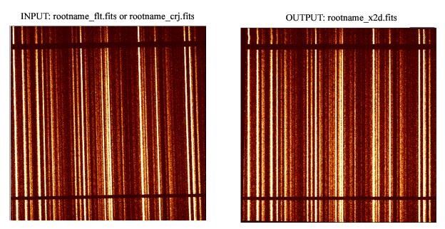
- Two-dimensional spectral extraction producing a flux-calibrated, rectified spectroscopic image (usually rootname_x2d.fits for MAMA data, rootname_sx2.fits for CCD) with distance along the slit running linearly along the Y axis and wavelength running linearly along the X axis, for spectroscopic first-order mode data. See Table 2.2 in the STIS Data Handbook.
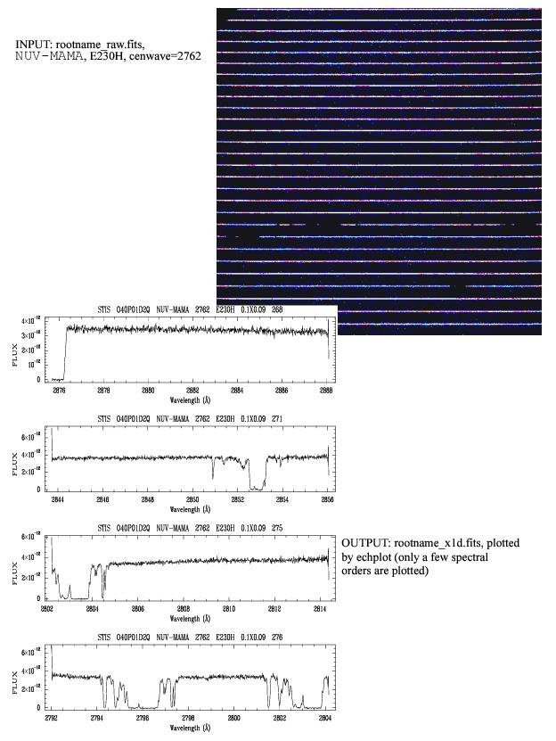
- One-dimensional spectral extraction producing a one-dimensional spectrum of flux versus wavelength (usually rootname_x1d.fits for MAMA data, rootname_sx1.fits for CCD), uninterpolated in wavelength space, but integrated across an extraction aperture in the spatial direction, for first-order and echelle spectroscopic data. See Table 2.2 in the STIS Data Handbook.
- Data taken in
TIME-TAGmode are corrected for the Doppler shift from the spacecraft motion and output as an uncalibrated event stream by the pipeline in a FITS binary table (rootname_tag.fits). The time-tag data stream is subsequently integrated in time to produce an uncalibratedACCUMmode image (rootname_raw.fits) which is then passed through standard calibration. To correctTIME-TAGspacecraft times to heliocentric times, refer to Section 5.6.1 in the STIS Data Handbook.
In addition, calstis performs two types of contemporaneous calibrations:
- For CCD exposures which have been
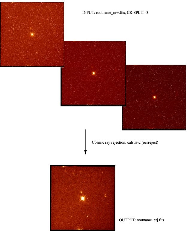
CR-SPLITor when multiple exposures have been taken, calstis combines the exposures, producing a cosmic ray rejected image (rootname_crj.fits) which is then passed through subsequent calibration steps (e.g., spectral extraction). - For spectroscopic exposures, calstis processes the associated wavecal exposure (see Section 3.3 Routine Wavecals) to determine the zero point offset of the wavelength and spatial scales in the science image, thereby correcting for thermal drifts and the lack of repeatability of the mode select mechanism. Raw wavecal data are stored in the file rootname_wav.fits to distinguish them from the uncalibrated science data in rootname_raw.fits.
Figure 15.1 through Figure 15.3 show example outputs from the calstis pipeline. The calstis program propagates statistical errors and tracks data quality flags through the calibration process. Although calstis is written in C, convenient Python wrapper programs are available as part of the stenv environment. These routines may be used to recreate the results of the pipeline (e.g., by re-running calstis in its entirety) or to customize the processing by running modular components such as as basic two-dimensional image reduction (basic2d), two-dimensional spectral extraction (x2d), one-dimensional spectral extraction (x1d), or cosmic ray rejection (ocrreject). Users can manually update the reference files listed in FITS headers by using the crds.bestrefs script. The calibration steps that calstis performs depends on the type of data. The action of each processing step is controlled by the value of a keyword flag in the FITS header (either OMIT or PERFORM). However, data obtained by available-but-unsupported-modes are calibrated only through flat-fielding in the pipeline.
Observers can retrieve STIS data from the MAST Portal, the HST Archive, or can use the Astropy module astroquery.mast to query and download data.
Between Spring 2001 and Fall 2016, calibrated data products for STIS were available through on-the-fly-reprocessing (OTFR), which replaced on-the-fly-calibration (OTFC). The OTFR system started with raw telemetry products, converted these to FITS files, and added the latest instrument calibrations.
Currently, the MAST archive maintains a cache of all STIS data that has been uniformly processed with the current instrumental calibration files. When new reference files become available, all affected data sets are promptly reprocessed and the cache is updated. This approach occasionally results in a delay between the submission of revised reference files and their application to the cached data. Users who require data calibrated with the most recently updated reference files may wish to consult with the STIS team to verify via the HST Help Desk when calibrated products made using these updated files will be available.
Calstis evolves and improves with time as we understand and characterize the on-orbit performance of STIS more fully. For details about the various changes made to the STIS calibration processes, please refer to the STIS Data Handbook.
-
STIS Instrument Handbook
- • Acknowledgments
- Chapter 1: Introduction
-
Chapter 2: Special Considerations for Cycle 33
- • 2.1 Impacts of Reduced Gyro Mode on Planning Observations
- • 2.2 STIS Performance Changes Pre- and Post-SM4
- • 2.3 New Capabilities for Cycle 33
- • 2.4 Use of Available-but-Unsupported Capabilities
- • 2.5 Choosing Between COS and STIS
- • 2.6 Scheduling Efficiency and Visit Orbit Limits
- • 2.7 MAMA Scheduling Policies
- • 2.8 Prime and Parallel Observing: MAMA Bright-Object Constraints
- • 2.9 STIS Snapshot Program Policies
- Chapter 3: STIS Capabilities, Design, Operations, and Observations
- Chapter 4: Spectroscopy
- Chapter 5: Imaging
- Chapter 6: Exposure Time Calculations
- Chapter 7: Feasibility and Detector Performance
-
Chapter 8: Target Acquisition
- • 8.1 Introduction
- • 8.2 STIS Onboard CCD Target Acquisitions - ACQ
- • 8.3 Onboard Target Acquisition Peakups - ACQ PEAK
- • 8.4 Determining Coordinates in the International Celestial Reference System (ICRS) Reference Frame
- • 8.5 Acquisition Examples
- • 8.6 STIS Post-Observation Target Acquisition Analysis
- Chapter 9: Overheads and Orbit-Time Determination
- Chapter 10: Summary and Checklist
- Chapter 11: Data Taking
-
Chapter 12: Special Uses of STIS
- • 12.1 Slitless First-Order Spectroscopy
- • 12.2 Long-Slit Echelle Spectroscopy
- • 12.3 Time-Resolved Observations
- • 12.4 Observing Too-Bright Objects with STIS
- • 12.5 High Signal-to-Noise Ratio Observations
- • 12.6 Improving the Sampling of the Line Spread Function
- • 12.7 Considerations for Observing Planetary Targets
- • 12.8 Special Considerations for Extended Targets
- • 12.9 Parallel Observing with STIS
- • 12.10 Coronagraphic Spectroscopy
- • 12.11 Coronagraphic Imaging - 50CORON
- • 12.12 Spatial Scans with the STIS CCD
-
Chapter 13: Spectroscopic Reference Material
- • 13.1 Introduction
- • 13.2 Using the Information in this Chapter
-
13.3 Gratings
- • First-Order Grating G750L
- • First-Order Grating G750M
- • First-Order Grating G430L
- • First-Order Grating G430M
- • First-Order Grating G230LB
- • Comparison of G230LB and G230L
- • First-Order Grating G230MB
- • Comparison of G230MB and G230M
- • First-Order Grating G230L
- • First-Order Grating G230M
- • First-Order Grating G140L
- • First-Order Grating G140M
- • Echelle Grating E230M
- • Echelle Grating E230H
- • Echelle Grating E140M
- • Echelle Grating E140H
- • PRISM
- • PRISM Wavelength Relationship
-
13.4 Apertures
- • 52X0.05 Aperture
- • 52X0.05E1 and 52X0.05D1 Pseudo-Apertures
- • 52X0.1 Aperture
- • 52X0.1E1 and 52X0.1D1 Pseudo-Apertures
- • 52X0.2 Aperture
- • 52X0.2E1, 52X0.2E2, and 52X0.2D1 Pseudo-Apertures
- • 52X0.5 Aperture
- • 52X0.5E1, 52X0.5E2, and 52X0.5D1 Pseudo-Apertures
- • 52X2 Aperture
- • 52X2E1, 52X2E2, and 52X2D1 Pseudo-Apertures
- • 52X0.2F1 Aperture
- • 0.2X0.06 Aperture
- • 0.2X0.2 Aperture
- • 0.2X0.09 Aperture
- • 6X0.2 Aperture
- • 0.1X0.03 Aperture
- • FP-SPLIT Slits 0.2X0.06FP(A-E) Apertures
- • FP-SPLIT Slits 0.2X0.2FP(A-E) Apertures
- • 31X0.05ND(A-C) Apertures
- • 0.2X0.05ND Aperture
- • 0.3X0.05ND Aperture
- • F25NDQ Aperture
- 13.5 Spatial Profiles
- 13.6 Line Spread Functions
- • 13.7 Spectral Purity, Order Confusion, and Peculiarities
- • 13.8 MAMA Spectroscopic Bright Object Limits
-
Chapter 14: Imaging Reference Material
- • 14.1 Introduction
- • 14.2 Using the Information in this Chapter
- 14.3 CCD
- 14.4 NUV-MAMA
-
14.5 FUV-MAMA
- • 25MAMA - FUV-MAMA, Clear
- • 25MAMAD1 - FUV-MAMA Pseudo-Aperture
- • F25ND3 - FUV-MAMA
- • F25ND5 - FUV-MAMA
- • F25NDQ - FUV-MAMA
- • F25QTZ - FUV-MAMA, Longpass
- • F25QTZD1 - FUV-MAMA, Longpass Pseudo-Aperture
- • F25SRF2 - FUV-MAMA, Longpass
- • F25SRF2D1 - FUV-MAMA, Longpass Pseudo-Aperture
- • F25LYA - FUV-MAMA, Lyman-alpha
- • 14.6 Image Mode Geometric Distortion
- • 14.7 Spatial Dependence of the STIS PSF
- • 14.8 MAMA Imaging Bright Object Limits
- Chapter 15: Overview of Pipeline Calibration
- Chapter 16: Accuracies
-
Chapter 17: Calibration Status and Plans
- • 17.1 Introduction
- • 17.2 Ground Testing and Calibration
- • 17.3 STIS Installation and Verification (SMOV2)
- • 17.4 Cycle 7 Calibration
- • 17.5 Cycle 8 Calibration
- • 17.6 Cycle 9 Calibration
- • 17.7 Cycle 10 Calibration
- • 17.8 Cycle 11 Calibration
- • 17.9 Cycle 12 Calibration
- • 17.10 SM4 and SMOV4 Calibration
- • 17.11 Cycle 17 Calibration Plan
- • 17.12 Cycle 18 Calibration Plan
- • 17.13 Cycle 19 Calibration Plan
- • 17.14 Cycle 20 Calibration Plan
- • 17.15 Cycle 21 Calibration Plan
- • 17.16 Cycle 22 Calibration Plan
- • 17.17 Cycle 23 Calibration Plan
- • 17.18 Cycle 24 Calibration Plan
- • 17.19 Cycle 25 Calibration Plan
- • 17.20 Cycle 26 Calibration Plan
- • 17.21 Cycle 27 Calibration Plan
- • 17.22 Cycle 28 Calibration Plan
- • 17.23 Cycle 29 Calibration Plan
- • 17.24 Cycle 30 Calibration Plan
- • 17.25 Cycle 31 Calibration Plan
- • 17.26 Cycle 32 Calibration Plan
- Appendix A: Available-But-Unsupported Spectroscopic Capabilities
- • Glossary


