F25NDQ Aperture
Description
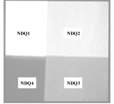
A neutral-density-filtered aperture for slitless 1st order MAMA spectroscopy of targets too bright to be observed with a clear aperture. This aperture is supported for all of the MAMA gratings and is available-but-unsupported for the CCD gratings. The F25NDQ filter is unique in that it is divided into four quadrants, each having a different neutral density factor. In clockwise order starting from the upper left, these are F25NDQ1, F25NDQ2, F25NDQ3, and F25NDQ4, where the number appended to each name is the approximate dex ND factor. Approximate dimensions of each quadrant and the default location of an external target in each quadrant are given in Table 13.34.
Special Considerations
The default aperture locations where the target is placed in each quadrant are significantly offset from the center of the detector in both the spatial and the dispersion directions. For observations at these nominal aperture locations, this will cause a significant shift in the wavelength coverage for any given grating setting. For example, when observing with G140L in F25NDQ1, wavelengths shorter than about 1330 Å will fall off the detector. Users may wish to use a POS-TARG to bring the target back closer to the center line of the detector. However, if the target would violate BOP restrictions in any quadrant of the aperture, the restrictions regarding pointing close to objects violating safety limits discussed in Chapter 7 and STIS ISR 2000-01 will apply. This latter rule renders the F25NDQ4 quadrant mostly useless, and the F25NDQ3 quadrant is redundant with the full field F25ND3 aperture, so in practice only the F25NDQ1 and F25NDQ2 quadrants are commonly used. Also the dividing lines between the quadrants are somewhat displaced from the center of the detector and are not quite parallel to the detector edges (see Figure 13.83), so observers for whom the exact locations of the quadrant boundaries are important should consult the Help Desk.
Table 13.34: NDQ Quadrant Dimensions and the Default Locations at which a Target Is Placed in Each Quadrant.
Aperture | Projected | Projected | Target X | Target Y |
| 13.4 | 9.7 | 198 | 756 |
| 13.8 | 15.1 | 712 | 753 |
| 11.4 | 15.3 | 686 | 254 |
| 11.8 | 9.5 | 195 | 248 |
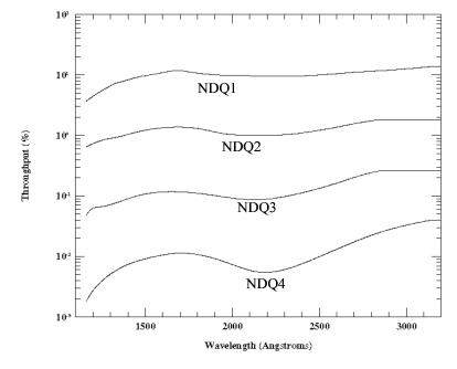
Table 13.35: F25NDQ Throughputs (%)
λ |
|
|
|
|
1161 | 3.69 | 0.65 | 0.05 | 0.002 |
1350 | 7.54 | 0.95 | 0.08 | 0.006 |
1550 | 10.24 | 1.29 | 0.11 | 0.010 |
1750 | 11.26 | 1.35 | 0.11 | 0.011 |
1950 | 9.88 | 1.07 | 0.10 | 0.008 |
2150 | 9.66 | 1.01 | 0.09 | 0.006 |
2350 | 9.54 | 1.06 | 0.10 | 0.007 |
2550 | 10.22 | 1.29 | 0.15 | 0.011 |
2750 | 11.30 | 1.66 | 0.22 | 0.020 |
2950 | 12.29 | 1.79 | 0.26 | 0.030 |
3150 | 13.73 | 1.79 | 0.26 | 0.040 |
Note: Aperture throughputs values for NDQ1 and NDQ4 at λ < 1330 Å and for NDQ2 and NDQ3 at λ > 2850 Å are extrapolated.
F25NDQ Aperture Throughputs vs. Wavelength.
-
STIS Instrument Handbook
- • Acknowledgments
- Chapter 1: Introduction
-
Chapter 2: Special Considerations for Cycle 33
- • 2.1 Impacts of Reduced Gyro Mode on Planning Observations
- • 2.2 STIS Performance Changes Pre- and Post-SM4
- • 2.3 New Capabilities for Cycle 33
- • 2.4 Use of Available-but-Unsupported Capabilities
- • 2.5 Choosing Between COS and STIS
- • 2.6 Scheduling Efficiency and Visit Orbit Limits
- • 2.7 MAMA Scheduling Policies
- • 2.8 Prime and Parallel Observing: MAMA Bright-Object Constraints
- • 2.9 STIS Snapshot Program Policies
- Chapter 3: STIS Capabilities, Design, Operations, and Observations
- Chapter 4: Spectroscopy
- Chapter 5: Imaging
- Chapter 6: Exposure Time Calculations
- Chapter 7: Feasibility and Detector Performance
-
Chapter 8: Target Acquisition
- • 8.1 Introduction
- • 8.2 STIS Onboard CCD Target Acquisitions - ACQ
- • 8.3 Onboard Target Acquisition Peakups - ACQ PEAK
- • 8.4 Determining Coordinates in the International Celestial Reference System (ICRS) Reference Frame
- • 8.5 Acquisition Examples
- • 8.6 STIS Post-Observation Target Acquisition Analysis
- Chapter 9: Overheads and Orbit-Time Determination
- Chapter 10: Summary and Checklist
- Chapter 11: Data Taking
-
Chapter 12: Special Uses of STIS
- • 12.1 Slitless First-Order Spectroscopy
- • 12.2 Long-Slit Echelle Spectroscopy
- • 12.3 Time-Resolved Observations
- • 12.4 Observing Too-Bright Objects with STIS
- • 12.5 High Signal-to-Noise Ratio Observations
- • 12.6 Improving the Sampling of the Line Spread Function
- • 12.7 Considerations for Observing Planetary Targets
- • 12.8 Special Considerations for Extended Targets
- • 12.9 Parallel Observing with STIS
- • 12.10 Coronagraphic Spectroscopy
- • 12.11 Coronagraphic Imaging - 50CORON
- • 12.12 Spatial Scans with the STIS CCD
-
Chapter 13: Spectroscopic Reference Material
- • 13.1 Introduction
- • 13.2 Using the Information in this Chapter
-
13.3 Gratings
- • First-Order Grating G750L
- • First-Order Grating G750M
- • First-Order Grating G430L
- • First-Order Grating G430M
- • First-Order Grating G230LB
- • Comparison of G230LB and G230L
- • First-Order Grating G230MB
- • Comparison of G230MB and G230M
- • First-Order Grating G230L
- • First-Order Grating G230M
- • First-Order Grating G140L
- • First-Order Grating G140M
- • Echelle Grating E230M
- • Echelle Grating E230H
- • Echelle Grating E140M
- • Echelle Grating E140H
- • PRISM
- • PRISM Wavelength Relationship
-
13.4 Apertures
- • 52X0.05 Aperture
- • 52X0.05E1 and 52X0.05D1 Pseudo-Apertures
- • 52X0.1 Aperture
- • 52X0.1E1 and 52X0.1D1 Pseudo-Apertures
- • 52X0.2 Aperture
- • 52X0.2E1, 52X0.2E2, and 52X0.2D1 Pseudo-Apertures
- • 52X0.5 Aperture
- • 52X0.5E1, 52X0.5E2, and 52X0.5D1 Pseudo-Apertures
- • 52X2 Aperture
- • 52X2E1, 52X2E2, and 52X2D1 Pseudo-Apertures
- • 52X0.2F1 Aperture
- • 0.2X0.06 Aperture
- • 0.2X0.2 Aperture
- • 0.2X0.09 Aperture
- • 6X0.2 Aperture
- • 0.1X0.03 Aperture
- • FP-SPLIT Slits 0.2X0.06FP(A-E) Apertures
- • FP-SPLIT Slits 0.2X0.2FP(A-E) Apertures
- • 31X0.05ND(A-C) Apertures
- • 0.2X0.05ND Aperture
- • 0.3X0.05ND Aperture
- • F25NDQ Aperture
- 13.5 Spatial Profiles
- 13.6 Line Spread Functions
- • 13.7 Spectral Purity, Order Confusion, and Peculiarities
- • 13.8 MAMA Spectroscopic Bright Object Limits
-
Chapter 14: Imaging Reference Material
- • 14.1 Introduction
- • 14.2 Using the Information in this Chapter
- 14.3 CCD
- 14.4 NUV-MAMA
-
14.5 FUV-MAMA
- • 25MAMA - FUV-MAMA, Clear
- • 25MAMAD1 - FUV-MAMA Pseudo-Aperture
- • F25ND3 - FUV-MAMA
- • F25ND5 - FUV-MAMA
- • F25NDQ - FUV-MAMA
- • F25QTZ - FUV-MAMA, Longpass
- • F25QTZD1 - FUV-MAMA, Longpass Pseudo-Aperture
- • F25SRF2 - FUV-MAMA, Longpass
- • F25SRF2D1 - FUV-MAMA, Longpass Pseudo-Aperture
- • F25LYA - FUV-MAMA, Lyman-alpha
- • 14.6 Image Mode Geometric Distortion
- • 14.7 Spatial Dependence of the STIS PSF
- • 14.8 MAMA Imaging Bright Object Limits
- Chapter 15: Overview of Pipeline Calibration
- Chapter 16: Accuracies
-
Chapter 17: Calibration Status and Plans
- • 17.1 Introduction
- • 17.2 Ground Testing and Calibration
- • 17.3 STIS Installation and Verification (SMOV2)
- • 17.4 Cycle 7 Calibration
- • 17.5 Cycle 8 Calibration
- • 17.6 Cycle 9 Calibration
- • 17.7 Cycle 10 Calibration
- • 17.8 Cycle 11 Calibration
- • 17.9 Cycle 12 Calibration
- • 17.10 SM4 and SMOV4 Calibration
- • 17.11 Cycle 17 Calibration Plan
- • 17.12 Cycle 18 Calibration Plan
- • 17.13 Cycle 19 Calibration Plan
- • 17.14 Cycle 20 Calibration Plan
- • 17.15 Cycle 21 Calibration Plan
- • 17.16 Cycle 22 Calibration Plan
- • 17.17 Cycle 23 Calibration Plan
- • 17.18 Cycle 24 Calibration Plan
- • 17.19 Cycle 25 Calibration Plan
- • 17.20 Cycle 26 Calibration Plan
- • 17.21 Cycle 27 Calibration Plan
- • 17.22 Cycle 28 Calibration Plan
- • 17.23 Cycle 29 Calibration Plan
- • 17.24 Cycle 30 Calibration Plan
- • 17.25 Cycle 31 Calibration Plan
- • 17.26 Cycle 32 Calibration Plan
- Appendix A: Available-But-Unsupported Spectroscopic Capabilities
- • Glossary

