8.2 STIS Onboard CCD Target Acquisitions - ACQ
8.2.1 How It Works
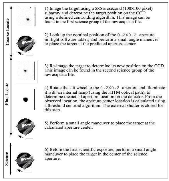
A target acquisition is performed at the beginning of a visit, and acquisition exposures are controlled by the Flight Software (FSW). Figure 8.3 highlights the basic steps in the acquisition process. The sequence comprises two discrete stages: the coarse-locate phase (steps 1–2) and the fine-locate phase (steps 3–5); a sixth step centers the target in the science aperture. The coarse-locate phase is performed to place the target as close as possible to the aperture center prior to the final telescope move. This step ensures that the final slew needed to move the target into the aperture is a small one, and it minimizes uncertainties in the calculation of the required slew caused by detector or optical distortions. The target acquisition steps are discussed in detail below.
- The target is located. A pair of 5 × 5 arcsecond (100 × 100 pixel) CCD images is taken of the sky using a user-selected filtered or unfiltered imaging aperture; for diffuse acquisitions, the field will be larger (see Section 8.2.2). The images are offset by 3 pixels in both X and Y to allow for removal of hot pixels via dithering. The flight software processes the images as needed (to realign the images, remove the bias level, flag bad pixels, and remove cosmic rays)1 and applies one of two possible finding algorithms to determine the coordinates of the target. The "bright" column at the edge of the acquisition field is an artifact of the subarray readout and is ignored by the flight software.
- The spacecraft is then moved to place the target at the nominal center of the
0.2X0.2slit. - The target is re-imaged and the target coordinates are redetermined. This second target location is performed to minimize the final slew in step 5, and to reduce the error associated with that slew.
- The location of the
0.2X0.2slit is determined relative to the target. The external shutter is closed (to prevent a possible overlight condition), the0.2X0.2slit is rotated into position by the slit wheel, and an image is obtained with the slit illuminated by a HITM line lamp (see Section 3.2.2 for a description of the HITM optical path). The slit image is processed and a finding algorithm is then used to determine the coordinates of the center of the slit. - The flight software calculates the offset between the target location and the
0.2X0.2slit, and performs a small angle maneuver of HST to place the target in the center of the aperture. - The object is placed in the science aperture (by a small angle maneuver using the known offset between the two slits) just prior to the execution of the scientific exposure. If another science exposure is made with a different aperture, the pointing is automatically adjusted to account for any difference in the locations of the science apertures.
An acquisition exposure produces data, which include the images of the target produced in steps 1 and 3, and the image of the
0.2X0.2 slit produced in step 4. These data will be returned to you with your scientific data as part of the pipeline products, and they can be analyzed with the tastis tool in stistools.8.2.2 Target Location Algorithms
STIS supports two basic types of acquisitions: point source acquisitions (ACQTYPE=POINT) and diffuse source acquisitions (ACQTYPE=DIFFUSE). Diffuse source acquisitions are appropriate for sources that exhibit smooth or peaked surface brightness on some size scale, such as centers of galaxies, some planets and planetary satellites (see Section 8.2.5), or nebulae.
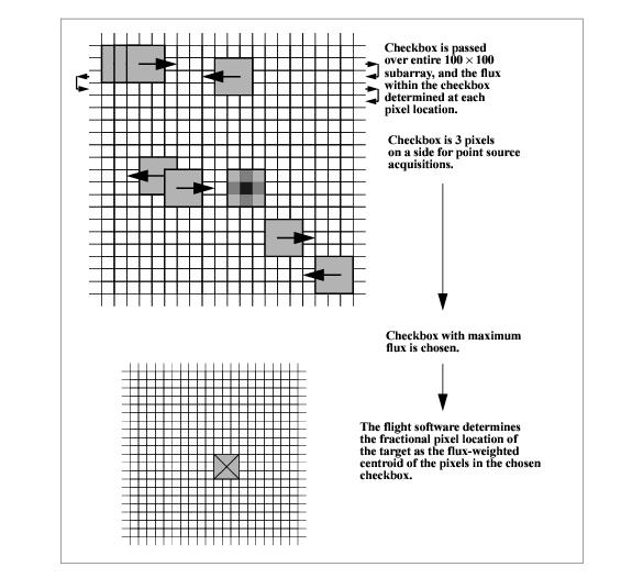
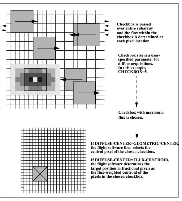
To locate the target, the flight software first passes a square checkbox over the image and determines the flux contained within the checkbox at each pixel in the subarray. The flight software then selects the checkbox with the maximum flux and determines the target center within that checkbox according to the type of acquisition specified.
Point Source Acquisition
For point source acquisitions (ACQTYPE=POINT), the checkbox size is fixed at 3 × 3 pixels (0.15 × 0.15 arcsecond) and the flight software determines the target location by finding the flux-weighted centroid of the pixels in the brightest checkbox (see Figure 8.4).
Diffuse Acquisition
For diffuse acquisitions (ACQTYPE=DIFFUSE), the flight software determines the target location either by finding the flux-weighted centroid of the pixels in the brightest checkbox or by determining the geometric center of the brightest checkbox (see Figure 8.5).
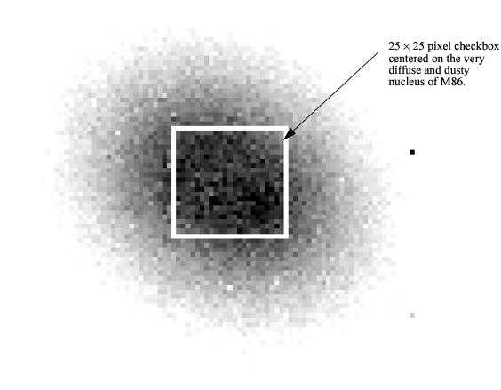
DIFFUSE-CENTER= GEOMETRIC-CENTER or FLUX-CENTROID) and the checkbox size. The user sets CHECKBOX=n, where n must be an odd number between 3 and 105: the checkbox will then have dimension n × n pixels. CHECKBOX should be set to the minimum size which ensures that the brightest checkbox will be the one centered on the region of interest (i.e., if your object is peaked within a region of 1 arcsecond, set CHECKBOX=21 [= (1arcsecond)/(0.05 arcsec/pix) + 1]. The maximum checkbox is 105 pixels on each side, or ~5 × 5 arcseconds. The subarray used for a diffuse-source acquisition target image is CHECKBOX+101 pixels on each side. The STIS Target Acquisition Simulator can be used to determine the optimal CHECKBOX size. For more information about determining the optimal checkbox size, please see section two of the November 2018 STIS STAN. Figure 8.6 shows a simulated example of a diffuse source, the nucleus of the galaxy M86, acquired using a diffuse-source acquisition.
CHECKBOX=25 produced good centering. Smaller values caused checkbox to center on local brightness enhancements offset from galaxy center.8.2.3 Selecting Target Acquisition Parameters
To plan your acquisition, you must select:
- The target you are going to acquire (scientific target or offset object).
- The type of acquisition, point or diffuse, and if you are performing a diffuse acquisition, the target acquisition centering algorithm and checkbox size.
- The filtered
APERTUREto be used for target imaging during the acquisition. - The exposure time for the image used to determine the location of the target.
- The program aperture, which determines if you need a peakup acquisition.
Figure 8.2 shows the flow of specifying a target acquisition scheme.
Selecting the Acquisition Object
The first step is to determine what object you are going to use for your target acquisition. Note that the STIS software will always acquire the brightest object in the 5 × 5 arcsecond search area. If your target is isolated, or if there are no brighter objects in the STIS bandpass you have selected (see below) within 5 arcseconds of your target, then you can acquire your target directly. If there are brighter targets nearby, then you will need to acquire an offset target (generally the brightest nearby star), and then perform a slew to the scientific target. The offset technique is also recommended for precise pointing to specific surface or atmospheric features for large (>~4 arcseconds) planetary targets such as Mars, Jupiter, and Saturn, with the offset target being a planetary satellite (see Section 8.2.5 for further details). Note that HST performs small angle maneuvers (SAM) quite accurately, with a 3 arcsecond maneuver having an error of 0.003 arcsecond, while a 2 arcminute maneuver (the maximum to ensure that a single set of guide stars can be used for both targets) yields a 0.02 arcsecond error. The offset should not significantly affect target acquisition centering accuracy even in the smallest echelle slits, and your target acquisition centering uncertainty will generally be dominated by your knowledge of the absolute offset between the acquisition star and your target. If you are uncertain whether a nearby object is brighter than your target in the STIS bandpass, it is safest to select an isolated object and perform your acquisition on it.
If you are observing a diffuse source, you should first check to see if there is a suitable star which you can use as an acquisition target; an offset can then be used to move to the desired position, as needed. If you wish to acquire a diffuse object directly, then it is important to know your source structure as seen at ~0.1 arcsecond resolution to properly plan your acquisition strategy if you need accurate (a few tenths of an arcsecond) centering. We recommend that you first check the HST archive to determine if your target has been observed by HST with WFPC1, WFPC2, WFC3, FOC, STIS or ACS. If it has, that exposure can be used to determine the optimal acquisition strategy using the Target Acquisition Simulator. If it has not yet been observed with HST, we suggest you take an early acquisition image, either with the STIS or with WFC3, which you can use to determine your optimal acquisition strategy. This is particularly important if your program requires placement of a narrow slit accurately on a diffuse object.
Once you have selected your acquisition object, you need to measure its coordinates (when possible, i.e., not for moving targets) in the Guide Star reference frame; information on measuring coordinates can be found in Section 8.4
To derive absolute coordinates, you can use TweakReg from the drizzlepac package to align your data to the GAIA catalog. This procedure is demonstrated in this notebook.
Note that the initial acquisition subarray is 5 arcseconds on each side; your target coordinates must be supplied accurately in the ICRS frame during Phase II to assure your target will be in the initial ACQ image, given that the initial guide star pointing accuracy is usually ~0.2–0.3 arcseconds but occasionally as large as 1 arcsecond.
Selecting the Acquisition Type
If you are acquiring a point-like object, you should select the optional parameter for a point source acquisition (ACQTYPE=POINT). This selection will find the flux-weighted centroid of the object using a 3 × 3 checkbox. If you are acquiring a diffuse object, you should select the diffuse source acquisition (ACQTYPE=DIFFUSE). A diffuse acquisition will also require selecting the target acquisition centering algorithm (DIFFUSE-CENTER= FLUX-CENTROID or GEOMETRIC-CENTER) and a checkbox size (CHECKBOX=3-105). Note that selecting a DIFFUSE acquisition with CHECKBOX=3 and DIFFUSE-CENTER=FLUX-CENTROID is equivalent to selecting the POINT source algorithm. A Target Acquisition Simulator is available to assist you in selecting the best checkbox size if you have an image at a similar resolution to that of STIS and in a similar bandpass.
Selecting the Imaging Aperture
The apertures available for target acquisitions are the same set that can be used for CCD imaging and are listed in Table 8.2 below. They include the visible longpass filter, the clear unfiltered aperture, the [O III] narrowband filter, the [O II] narrowband filter, and the neutral-density filters which provide attenuations for bright sources of 10–3 and 10–5. F28X50LP is the preferred target acquisition aperture. The longpass filter is preferred (compared to the clear 50CCD aperture) because it blocks the UV photons, which can otherwise elevate the detector dark count in the subsequent scientific exposures (see Section 7.3.10). For bright sources which saturate the CCD in 0.1 second with the longpass filter (see Table 8.3), you can use either the narrowband [O III] (F28X50OIII) or [O II] (F28X50OII) filters as the acquisition aperture, or one of the neutral density filters. The [O II] and [O III] filters can also be used to locate the target in the light of an emission line. Note that the [O III] filter has a large red leak at λ > 10,000 Å (see Chapter 14), so it should be used with caution; the [O II] filter has no measurable red leak.
Table 8.2: Apertures for Target Acquisitions.
Aperture Name | Filter Type | Comment |
| Optical longpass | Preferred target acquisition aperture |
| [O | Use for bright sources or to center on emission line structure |
| [O | Use for bright sources or to center on emission line structure |
| Neutral density, ND=10–3 | Use only for targets too bright for other filters |
| Neutral density, ND=10–5 | Use only for targets too bright for other filters |
| Clear | Use for acquisitions of faintest sources only |
We recommend the longpass F28X50LP filter for all target acquisitions of sources with V magnitudes between 10 and 23.
Determining Exposure Time for the ACQ Exposure
To achieve robust target location:
- A minimum signal-to-noise ratio of at least 40 (over the checkbox) or 1700 electrons (425 DN) must be obtained on each target image obtained during the
ACQexposure. Higher signal-to-noise ratios should be considered if practical (see below). - For
DIFFUSEacquisitions with large checkbox sizes (i.e.,CHECKBOX> 9), a contrast relative to surrounding regions of at least 40 e–/pix (or equivalently 10 DN/pix) must be obtained for the region of the source being "found." - The target image cannot be allowed to saturate the CCD full well (144,000 electrons).
- The exposure time must be less than 5 minutes for point source acquisitions and less than the maximum allowed (see below) for diffuse acquisitions.
- A
CCDGAINof 4 is used for all acquisition images.
It should be considered that the count rates recommended above are the minimum count rates needed for the acquisition to have a high chance of success. However, obtaining ACQ images with significantly higher signal-to-noise ratios than these minima do provide an additional degree of protection against failures caused by a poor estimate of the source count rate or by a bad initial pointing that puts the target just outside the acquisition subarray (in the latter case, the diffraction spikes or the wings of the PSF may well be detected in the initial image and moved to the detector center, allowing the ACQ to succeed during the fine-locate phase). Such deeper exposures are therefore recommended if the additional overheads are small compared to the overhead time for ACQ exposures (typically 6 minutes), and if there is no chance of saturating the CCD. For a point source, the full well limit of 144,000 electrons in the central pixel corresponds to an ETC S/N estimate of about 400:1.
The maximum possible exposure time for a point source acquisition (ACQTYPE=POINT) exposure is 5 minutes; this limit restricts acquisitions to sources brighter than 24.5 mag in V. This limit is imposed because, for longer exposure times, the target acquisitions become compromised by coincident cosmic ray impacts, which will lead to acquisition failures. The maximum possible exposure time for a diffuse acquisition depends on the checkbox and is given by:
| t_{max} = [5 × 100 / (101 + CHECKBOX)]\ \rm minutes\ . |
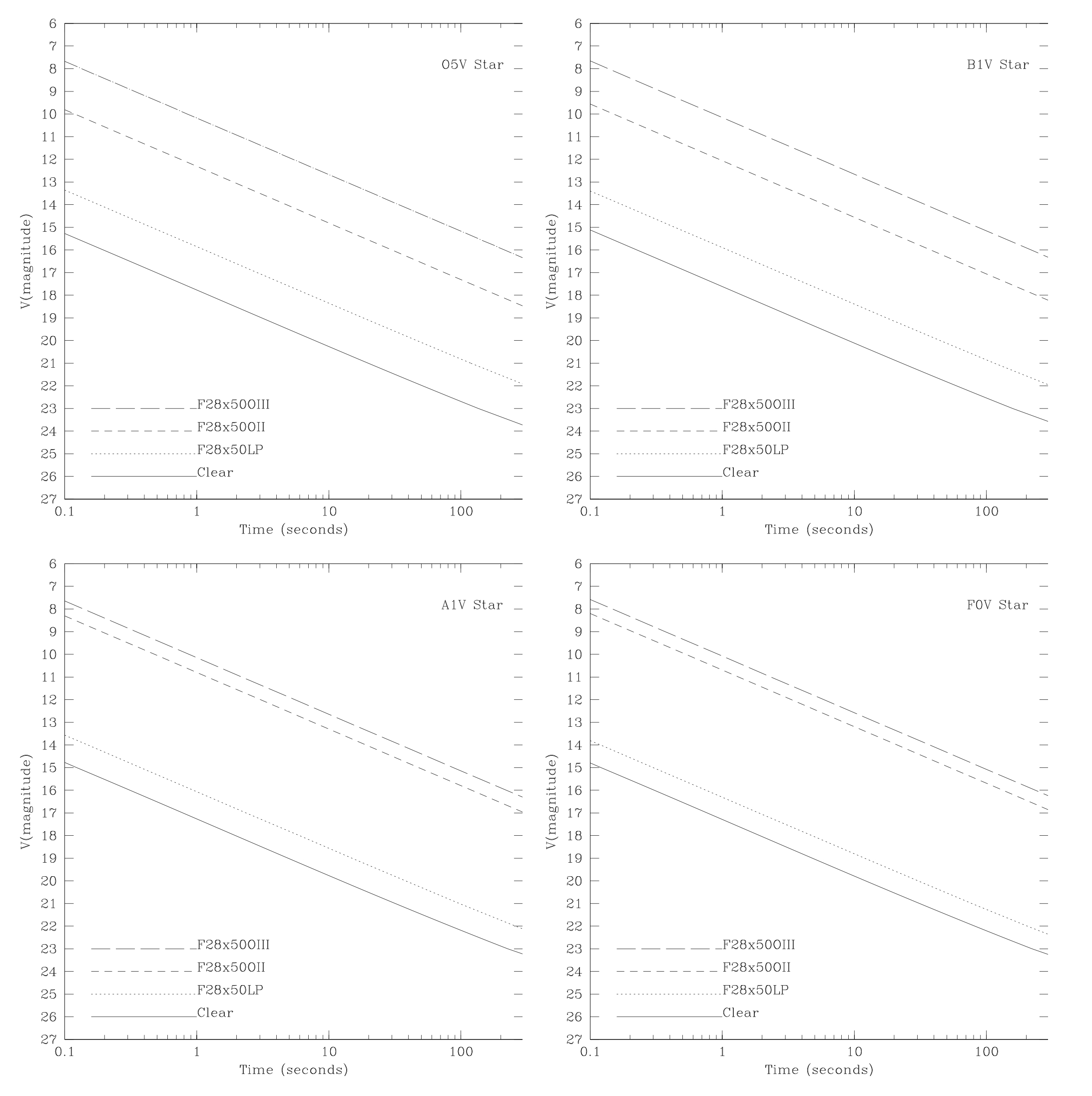
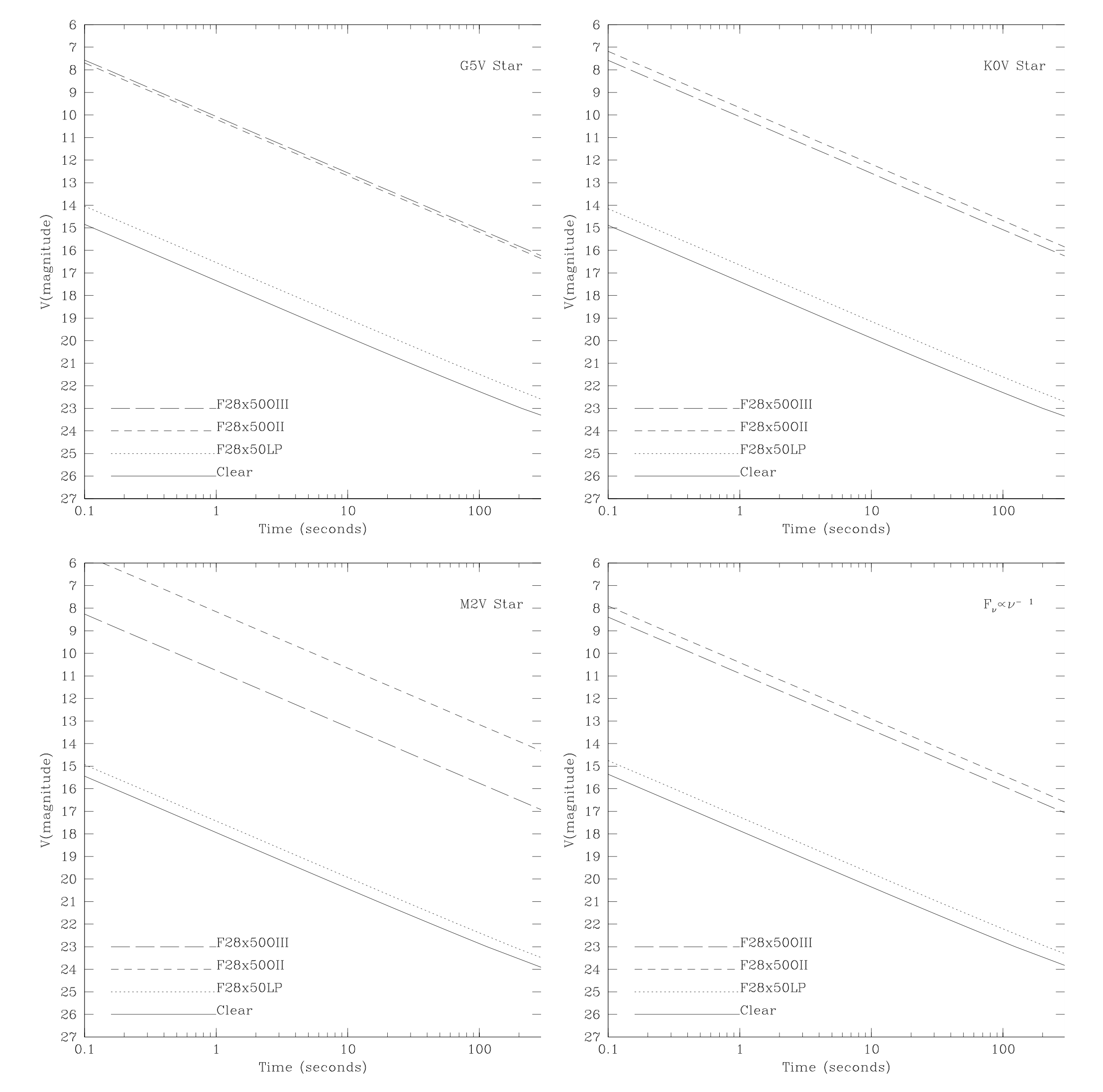
The minimum exposure time allowed for an acquisition is 0.1 second. Table 8.3 gives the limiting magnitudes at which the CCD will saturate in a 0.1 second exposure; sources brighter than these limits cannot be acquired with the CCD using these filters. Remember that the ND filters can also be used to acquire targets; these filters provide attenuations of 10–3 (7.5 magnitudes) and 10–5 (12.5 magnitudes) relative to the clear (50CCD) filter. Note that the ND filters are contained in the slit wheel with other slits and apertures, and so cannot be used in conjunction with other filters. The table illustrates that it is possible to image any star using a filter from the suite, including the neutral-density filters, available for STIS.
Table 8.3: V Magnitude Limits for Saturation of a 0.1 Second CCD Exposure Time as a Function of Aperture.
Spectral Type | Limiting Magnitude | ||||
|
|
|
|
| |
O5 V | 10.0 | 8.0 | 4.7 | 2.3 | 2.9/–3.5 |
B1 V | 9.8 | 8.0 | 4.5 | 2.3 | 2.8/–3.5 |
B5 V | 9.7 | 8.0 | 4.1 | 2.3 | 2.6/–3.6 |
B8 V | 9.5 | 8.0 | 3.7 | 2.3 | 2.5/–3.7 |
A1 V | 9.4 | 8.0 | 3.2 | 2.2 | 2.5/–3.7 |
A3 V | 9.4 | 8.0 | 3.1 | 2.2 | 2.4/–3.7 |
A5 V | 9.3 | 8.0 | 3.1 | 2.2 | 2.4/–3.7 |
F0 V | 9.3 | 8.1 | 3.1 | 2.0 | 2.4/–3.6 |
F5 V | 9.3 | 8.2 | 3.0 | 2.0 | 2.4/–3.5 |
F8 V | 9.3 | 8.2 | 2.9 | 1.9 | 2.4/–3.5 |
1G2 V | 9.3 | 8.3 | 2.7 | 1.9 | 2.4/–3.5 |
2G8 V | 9.3 | 8.4 | 2.1 | 1.7 | 2.4/–3.4 |
3K2 V | 9.3 | 8.4 | 2.0 | 1.7 | 2.4/–3.3 |
4KM III | 9.4 | 9.0 | 1.6 | 1.7 | 2.8/–2.7 |
Power Law | 9.4 | 8.6 | 3.4 | 1.7 | 2.7/–3.3 |
1 Calculations performed using the Solar template available in the STIS ETC.
2 Calculations performed using IUE data for the star Tau Ceti.
3 Calculations performed using IUE data for the star Epsilon Eri.
4 Calculations performed using IUE data for nine IUE stars of these types.
Figure 8.7 and Figure 8.8 can help you estimate exposure times—they plot exposure time versus V magnitude to achieve a signal-to-noise ratio of 40 for stars having a range of spectral types, for the clear, longpass, [O III], and [O II] filters. To determine the exact exposure time for your target, you should use the STIS TA ETC (see Section 8.5). Note that the overheads in target acquisitions are substantially longer than most exposure times, so as long as you do not approach saturation (i.e., come within 30% of the full well) you should increase your exposure time by a factor of at least a few above the minimum required (e.g., if the exposure time to obtain a S/N of 40 is 0.3 second, then you should lengthen it to 1 second if no saturation occurs). Also consider whether a shorter exposure in a higher throughput filter might give better S/N (see Table 8.3 for the brightest magnitude as a function of filter and target spectral type which can be observed without saturating the acquisition exposure). The exposure time entered into your Phase II template is the time for each of the two exposures in the ACQ sequence, unlike the case of CR-SPLIT observations where it is the total time.
8.2.4 Specifying Acquisitions in Phase II
Acquisition exposures must be specified during Phase II before the scientific exposures for which they are intended. The user requests a target acquisition exposure by specifying MODE=ACQ on the APT Phase II exposure parameters page and setting ACQTYPE. The default is ACQTYPE=POINT, but ACQTYPE=DIFFUSE is also an option. If ACQTYPE=DIFFUSE is selected, the observer must also specify DIFFUSE-CENTER and CHECKBOX.
ETC and Phase II examples are provided in Section 8.5.
8.2.5 Solar System Acquisitions
The ACQ procedure can be used for solar system targets as well as fixed targets. The difference is in the specification of the target position, which is outlined in Chapter 3 of the HST Phase II Proposal Instructions. For satellites less than 0.1 arcsecond in diameter, a point source ACQ is sufficient. For satellites of greater diameter, ACQTYPE=DIFFUSE with DIFFUSE-CENTER=GEOMETRIC and a CHECKBOX size chosen to match the satellite diameter are recommended. To acquire a planetary feature or a satellite transiting the planet, another satellite in the system can generally be used as an offset target. If precise pointing to a specific feature is not required, then blind pointing (which is generally accurate to ~0.2–1.0 arcseconds) can be used for larger targets such as Mars, Jupiter, and Saturn. The types of acquisitions recommended for the most common solar system targets is summarized in Table 8.4.
Table 8.4: Solar System Acquisitions.
Target | Type of Acquisition | Offset Target |
Venus | Offset target | Star |
Mars | Offset target | Deimos |
Jupiter | Offset target | Galilean satellite |
Saturn | Offset target | Satellite |
Uranus | Diffuse source | |
Neptune | Diffuse source | |
Satellite or asteroid <~0.1 arcseconds | Point source | |
Satellite or asteroid >~0.1 arcseconds | Diffuse source | |
Transiting satellite | Offset target | Another satellite |
Comet | Diffuse source |
The coordinates of the planets and their satellites are derived from ephemerides obtained by STScI from JPL. The accuracies of the ephemerides are maintained by JPL on their Planetary Satellite Ephemerides page; see also the JPL Horizons service for computing ephemerides.
Your Program Coordinator can provide detailed information on ephemerides and tracking for your observations.
Special care must be taken when tracking satellites with rapidly changing direction or velocity. Observers should be aware that moving targets are tracked by HST with the assumption that the object is moving on a linear track with constant velocity. Depending on the visit structure, the same linear track may continue through several exposures. The scheduling software sets a generally appropriate limit on the duration of a linear track which depends on the target being tracked, but not on details of the target motion at the time. In some situations (for example, near the inflection point of an orbit), the approximation could result in inadequate tracking when using a narrow slit. If this may be a problem, the observer can consult the proposal’s designated Program Coordinator to find out how long the same track will be used for a series of exposures, and whether it is possible to break the visit into shorter tracks. Alternatively, one can plan to observe during a more linear part of the orbit.
Acquisition exposure times can be accurately estimated using the STIS Target Acquisition ETC: use the Kurucz model G2 V (solar spectrum), and normalize it using the V magnitude for point-like (≤0.1 arcsecond) objects or the V magnitude per arcsecond2 and the appropriate target size in arcseconds for more extended targets.
1 The processing done by the FSW is rudimentary: a single, pre-determined, bias number is subtracted, bad pixels are set to the average of the 4 adjacent pixels, negative-valued pixels are set to zero, and each pixel is assigned the minimum from the two images (as a form of cosmic ray and hot pixel rejection). Hence, ACQ exposures are not suited for accurate photometry.
-
STIS Instrument Handbook
- • Acknowledgments
- Chapter 1: Introduction
-
Chapter 2: Special Considerations for Cycle 33
- • 2.1 Impacts of Reduced Gyro Mode on Planning Observations
- • 2.2 STIS Performance Changes Pre- and Post-SM4
- • 2.3 New Capabilities for Cycle 33
- • 2.4 Use of Available-but-Unsupported Capabilities
- • 2.5 Choosing Between COS and STIS
- • 2.6 Scheduling Efficiency and Visit Orbit Limits
- • 2.7 MAMA Scheduling Policies
- • 2.8 Prime and Parallel Observing: MAMA Bright-Object Constraints
- • 2.9 STIS Snapshot Program Policies
- Chapter 3: STIS Capabilities, Design, Operations, and Observations
- Chapter 4: Spectroscopy
- Chapter 5: Imaging
- Chapter 6: Exposure Time Calculations
- Chapter 7: Feasibility and Detector Performance
-
Chapter 8: Target Acquisition
- • 8.1 Introduction
- • 8.2 STIS Onboard CCD Target Acquisitions - ACQ
- • 8.3 Onboard Target Acquisition Peakups - ACQ PEAK
- • 8.4 Determining Coordinates in the International Celestial Reference System (ICRS) Reference Frame
- • 8.5 Acquisition Examples
- • 8.6 STIS Post-Observation Target Acquisition Analysis
- Chapter 9: Overheads and Orbit-Time Determination
- Chapter 10: Summary and Checklist
- Chapter 11: Data Taking
-
Chapter 12: Special Uses of STIS
- • 12.1 Slitless First-Order Spectroscopy
- • 12.2 Long-Slit Echelle Spectroscopy
- • 12.3 Time-Resolved Observations
- • 12.4 Observing Too-Bright Objects with STIS
- • 12.5 High Signal-to-Noise Ratio Observations
- • 12.6 Improving the Sampling of the Line Spread Function
- • 12.7 Considerations for Observing Planetary Targets
- • 12.8 Special Considerations for Extended Targets
- • 12.9 Parallel Observing with STIS
- • 12.10 Coronagraphic Spectroscopy
- • 12.11 Coronagraphic Imaging - 50CORON
- • 12.12 Spatial Scans with the STIS CCD
-
Chapter 13: Spectroscopic Reference Material
- • 13.1 Introduction
- • 13.2 Using the Information in this Chapter
-
13.3 Gratings
- • First-Order Grating G750L
- • First-Order Grating G750M
- • First-Order Grating G430L
- • First-Order Grating G430M
- • First-Order Grating G230LB
- • Comparison of G230LB and G230L
- • First-Order Grating G230MB
- • Comparison of G230MB and G230M
- • First-Order Grating G230L
- • First-Order Grating G230M
- • First-Order Grating G140L
- • First-Order Grating G140M
- • Echelle Grating E230M
- • Echelle Grating E230H
- • Echelle Grating E140M
- • Echelle Grating E140H
- • PRISM
- • PRISM Wavelength Relationship
-
13.4 Apertures
- • 52X0.05 Aperture
- • 52X0.05E1 and 52X0.05D1 Pseudo-Apertures
- • 52X0.1 Aperture
- • 52X0.1E1 and 52X0.1D1 Pseudo-Apertures
- • 52X0.2 Aperture
- • 52X0.2E1, 52X0.2E2, and 52X0.2D1 Pseudo-Apertures
- • 52X0.5 Aperture
- • 52X0.5E1, 52X0.5E2, and 52X0.5D1 Pseudo-Apertures
- • 52X2 Aperture
- • 52X2E1, 52X2E2, and 52X2D1 Pseudo-Apertures
- • 52X0.2F1 Aperture
- • 0.2X0.06 Aperture
- • 0.2X0.2 Aperture
- • 0.2X0.09 Aperture
- • 6X0.2 Aperture
- • 0.1X0.03 Aperture
- • FP-SPLIT Slits 0.2X0.06FP(A-E) Apertures
- • FP-SPLIT Slits 0.2X0.2FP(A-E) Apertures
- • 31X0.05ND(A-C) Apertures
- • 0.2X0.05ND Aperture
- • 0.3X0.05ND Aperture
- • F25NDQ Aperture
- 13.5 Spatial Profiles
- 13.6 Line Spread Functions
- • 13.7 Spectral Purity, Order Confusion, and Peculiarities
- • 13.8 MAMA Spectroscopic Bright Object Limits
-
Chapter 14: Imaging Reference Material
- • 14.1 Introduction
- • 14.2 Using the Information in this Chapter
- 14.3 CCD
- 14.4 NUV-MAMA
-
14.5 FUV-MAMA
- • 25MAMA - FUV-MAMA, Clear
- • 25MAMAD1 - FUV-MAMA Pseudo-Aperture
- • F25ND3 - FUV-MAMA
- • F25ND5 - FUV-MAMA
- • F25NDQ - FUV-MAMA
- • F25QTZ - FUV-MAMA, Longpass
- • F25QTZD1 - FUV-MAMA, Longpass Pseudo-Aperture
- • F25SRF2 - FUV-MAMA, Longpass
- • F25SRF2D1 - FUV-MAMA, Longpass Pseudo-Aperture
- • F25LYA - FUV-MAMA, Lyman-alpha
- • 14.6 Image Mode Geometric Distortion
- • 14.7 Spatial Dependence of the STIS PSF
- • 14.8 MAMA Imaging Bright Object Limits
- Chapter 15: Overview of Pipeline Calibration
- Chapter 16: Accuracies
-
Chapter 17: Calibration Status and Plans
- • 17.1 Introduction
- • 17.2 Ground Testing and Calibration
- • 17.3 STIS Installation and Verification (SMOV2)
- • 17.4 Cycle 7 Calibration
- • 17.5 Cycle 8 Calibration
- • 17.6 Cycle 9 Calibration
- • 17.7 Cycle 10 Calibration
- • 17.8 Cycle 11 Calibration
- • 17.9 Cycle 12 Calibration
- • 17.10 SM4 and SMOV4 Calibration
- • 17.11 Cycle 17 Calibration Plan
- • 17.12 Cycle 18 Calibration Plan
- • 17.13 Cycle 19 Calibration Plan
- • 17.14 Cycle 20 Calibration Plan
- • 17.15 Cycle 21 Calibration Plan
- • 17.16 Cycle 22 Calibration Plan
- • 17.17 Cycle 23 Calibration Plan
- • 17.18 Cycle 24 Calibration Plan
- • 17.19 Cycle 25 Calibration Plan
- • 17.20 Cycle 26 Calibration Plan
- • 17.21 Cycle 27 Calibration Plan
- • 17.22 Cycle 28 Calibration Plan
- • 17.23 Cycle 29 Calibration Plan
- • 17.24 Cycle 30 Calibration Plan
- • 17.25 Cycle 31 Calibration Plan
- • 17.26 Cycle 32 Calibration Plan
- Appendix A: Available-But-Unsupported Spectroscopic Capabilities
- • Glossary
