13.7 Spectral Purity, Order Confusion, and Peculiarities
If the PSF had an infinitely small FWHM and no extended wings, a point source would produce a spectrogram with infinitesimal extension in the spatial direction. Furthermore, the spectral resolution would be essentially the theoretical limit of the spectrograph, independent of the entrance slit. In practice, the Optical Telescope Assembly PSF is wider and more complex, and there is scattered light from both the gratings and the detector itself, leading to decreased spectral resolution and spectral purity.
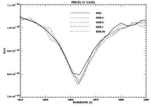
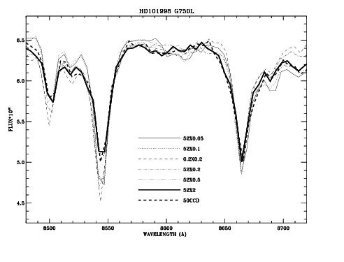
In Figure 13.94 we have plotted Hβ in the white dwarf Feige 110 observed with the G430L grating and five entrance slits with widths between 2" and 0."05. The spectrum observed through the 0."05 and 0."1 slits can be considered spectrally pure (0."1 corresponds to 2 pixels on the CCD and 0."05 corresponds to 2 pixels on the MAMAs). Observations with the 0."2 slits are still reasonably pure but larger slit widths lead to significant impurity. This becomes evident from the increasing flux in the line core with increasing slit width. The maximum spectral purity is achieved with entrance slits of 0."2 width or smaller. Similar results can be seen in Figure 13.95 which shows the calcium triplet regions. Observers wishing to study spectral lines of continuum sources should always consider using small entrance slits.
13.7.1 Recommendations for Stellar Observations with Narrow Slits
In assessing the trade between the better spectral purity of small slits and the higher throughput and photometric precision of larger slits, the following should be kept in mind:
- Choose a slit that meets the requirements for photometric precision.
- Avoid the
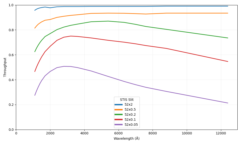
52X0.05slit with theG750modes, since the Airy core of the point spread function is much larger than the slit size and the resulting light losses may exceed a factor of 5 in comparison with the52X2slit. Furthermore, the nominal resolution of 2 pixels is a match to a 0.1 arcsec slit width for the CCD modes. - Longer wavelength observations require wider slits to avoid light loss problems as the point spread function enlarges. Beyond ~5000 Å, a rapid loss of light is possible even when a
52X0.1slit is used (see Figure 13.95b). In a test of medium dispersion modes, a loss of 10% was found near 4000 Å, but this increased to 25% by 8500 Å. - As a stellar target may not be perfectly centered, pipeline fluxes may, in general, be treated as lower limits. Exceptions are the CCD
G430LandG750Lmodes which utilize a Lyot stop.
More complete details on these points can be found in STIS ISR 1998-20 by R. Bohlin and G. Hartig. Regardless of the size of the slit, it is important to remember that a peakup will ensure the greatest wavelength accuracy, since an offset of the target in the dispersion direction will be miscalibrated as an offset of the wavelength scale (see Section 8.1.1 and Section 8.3.1).
13.7.2 Order Overlap and Scattered Light for Echelle Gratings
As with most other echelle spectrographs, STIS echelle data are affected by spectral order overlap at the shortest wavelengths where adjacent spectral orders are not well separated. Echelle observations of continuum sources taken slitless or with a 2X2 entrance slit suffer from severe order overlap. Therefore, an entrance slit of 0."2 or smaller height should be used.
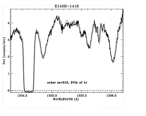
Figure 13.96 demonstrates the difference in resolution for a narrow absorption line for BD+75°325 observed in the 0.2X0.2 slit vs. a 0.2X0.09 slit. Any difference in the effect of impure light on the depth of the line profiles is less than ~1% of the continuum. An extraction height of 7 pixels is used, and the 0.2X0.09 aperture spectrum is multiplied by 1.28 to compensate for the lower transmission. A slight wavelength shift is maintained to improve visibility.
0.2X0.2 (solid line) and 0.2X0.09 (dotted line) Aperture Spectra of BD+75°325 in the E140H-1416 Mode.
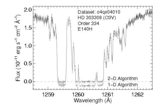
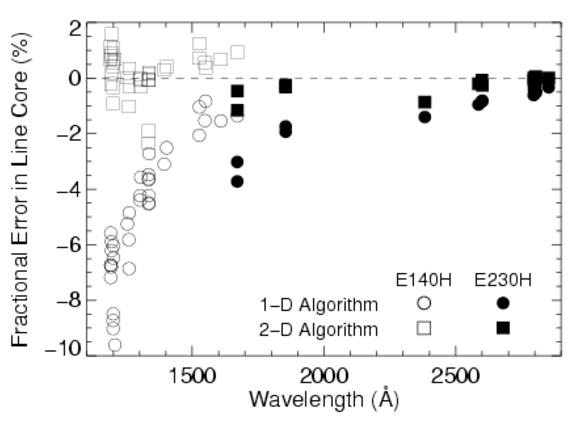
E140M and E140H modes do have appreciable scatter; 33% of the light scattered at 1235 Å for E140M and 15% for E140H; at 1600 Å this drops to ~12% and 8%, respectively. The STScI provides an ETC, which predicts global and net countrates to sufficient accuracy for planning purposes. An estimate of the net S/N and the net + scattered light in an echelle observation are produced for a specified input spectrum, including an approximation to the scattered component.An "algorithm" parameter has been added to the x1d spectral extraction task in calstis. Changing this parameter from "unweighted" to sc2d enables a new two-dimensional background subtraction algorithm that was designed by Don Lindler (Sigma Space Corporation) and Chuck Bowers (Goddard Space Flight Center). Alternatively, calstis can be run on the new data with SC2DCORR set to PERFORM in the primary header (see Section 3.4.20 of the STIS Data Handbook). Figure 13.97 shows the dramatic improvement achieved with the use of this new algorithm. Figure 13.98 summarizes the fractional error in saturated line cores as a function of wavelength and grating for both algorithms. Errors for the medium-resolution gratings are comparable to errors for the high-resolution gratings.
Briefly, the new algorithm works as follows: a 2-D raw image is fit with a 2-D model, reconstructed at each iteration from the best current estimate of the extracted spectrum folded through a semi-empirical simulation of STIS optical properties. Self-consistency between the 2-D model and the extracted spectrum is achieved via iteration. An analogous model containing only scattered light is then constructed using only the echelle scatter light outside an 11 pixel-wide vertical window centered on each order. This 2-D scattered-light model is subtracted from the raw data and the final spectrum is obtained using standard 1-D extraction.
Construction of the 2-D model during each iteration involves several steps. Counts in the 1-D extracted spectrum are mapped back to their idealized origin in hypothetical echelle orders that extend beyond the edge of the physical detector. Echelle scatter is modelled by redistributing extracted counts along diagonal lines of constant wavelength, using echelle line spread functions. Post-echelle smearing along columns is modelled by independently convolving each column with a smoothing kernel. Scattering due to the aperture-truncated telescope PSF, isotropic detector halo, and pre-echelle scattering by the cross-disperser are treated by 2-D convolution with a kernel constructed from these components.
13.7.3 Spectroscopic Mode Peculiarities
During the original SMOV and initial observations, a number of first-order mode spectra have been obtained that show additional features that may affect the scientific goals of the observations. One class of spectroscopic images shows diffraction structure of the PSF re-imaged at the various STIS detectors. A second class, commonly referred to as railroad tracks, displays additional "spectra" displaced from and parallel to the primary spectrum. Some examples and impacts are presented below.
PSF Re-Imaging
The STIS corrector mirrors re-image the OTA PSF at an intermediate focus within STIS at the location of the slit wheel. This intermediate image is re-imaged to one of the detectors via the selected mode, either imaging or spectroscopic. Any PSF structure present in the slit plane image will be re-imaged at the detectors; however, its appearance in a final spectrum or image depends on the selected mode and the slit or aperture used.
In the imaging modes, little PSF diffraction structure is apparent, since the available filters are typically relatively broad band, smoothing out any structure. The spectroscopic modes, however, create a series of near monochromatic images at the detector plane and the PSF diffraction structure can be detected with the two dimensional STIS detectors.
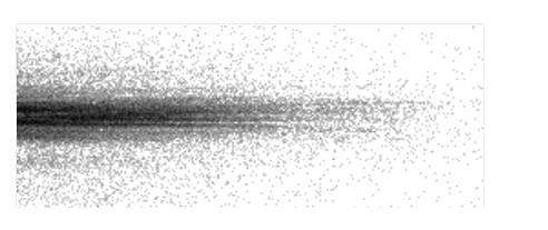
Point Source: Figure 13.99 shows the spectrum of a point source target, using G140L and slit 52X0.05.
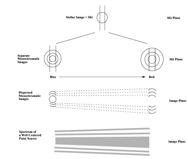
Figure 13.100 illustrates how such fringes are created at the detector. At each wavelength, the portion of the PSF at the slit plane which passes the slit is re-imaged onto the detector. The envelope of all such PSF portions forms the complete image at the detector, as shown. The characteristic fringe separation, proportional to wavelength, is expected as the diffraction structure in the PSF increases with wavelength as shown. In the medium-resolution modes, with much less bandpass than the low-resolution modes, the tilt of the fringes is much less—they are nearly parallel to the primary spectrum.
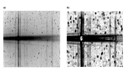
Out of slit point source: Figure 13.101 shows the spectrum (G140L) of a stellar source, in which the target was mis-located and not nominally in the 52X0.05 slit. While the target center was not located in the slit, the extended PSF structure did cover the slit opening and was transmitted and re-imaged at the detector plane. This image has been processed and log stretched to enhance the faint fringe structure which is apparent.
G750L. The images were processed and log stretched to enhance the fringe appearance. Divergent fringes are apparent above and below the spectrum. A principal component of the "spectrum" consists of changes in the upper and lower portions of the first Airy ring, seen clearly separated at the long wavelength end of the spectrum. (See STIS ISR 2006-02.) These two fringes converge at shorter wavelengths forming a single fringe which overlies the much fainter, off-core portion of the galaxy. The evident blueness of the core spectrum in this particular source makes the combined blue fringes much brighter than the combination of the separated red fringes.
Impact
Diffraction structure in the PSF will set a limit to extracting spectra near a bright source. Blocking the bright source, either by using a coronagraphic aperture or by moving the bright source out of the slit does not remove the inherent, adjacent PSF or diffraction structure. In the case of a faint companion adjacent to a bright, primary source, note that the spectra of the primary and companion will be parallel while the PSF fringes will be tilted. This is especially true in the low resolution modes and may allow the unambiguous identification of a faint companion even in the presence of comparably bright PSF structure.
13.7.4 Railroad Tracks
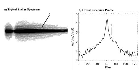
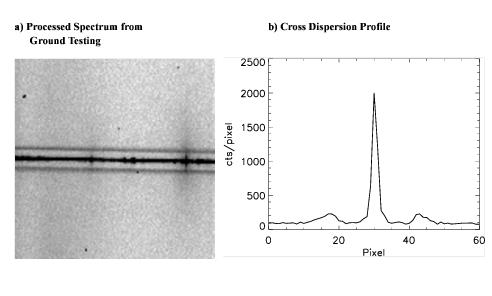
Figure 13.103 (panel a) shows a processed spectrum of a continuum lamp in mode G750M, λC = 10,363 and slit 0.1X0.2 obtained during ground testing. Beside the spectrum, two adjacent, parallel, secondary spectra are seen symmetrically displaced about 13 pixels from the lamp spectrum. Panel b shows a cross dispersion profile illustrating the magnitude and shape of the spectra. The secondary spectra have peak intensities about 8% of the primary spectrum but are broader and asymmetric. This was the only example of this peculiar condition noticed during ground testing; however, subsequent review showed one additional example also obtained during ground testing. This second case was a similar continuum lamp spectrum using G750M, λC = 7795, with the same slit. Secondary spectra were ~8% and 3% (peak intensity) of the primary peak intensity.
G230LB and the CCD. The target was a very red star. The parallel, secondary spectra are visible at a level of about 8% of peak intensity.The cause of these secondary spectra in these three observations is not known. The three cases observed have all been with the CCD; no MAMA examples have been obtained. Other observations in these modes under similar conditions have not shown such effects. In all cases, a red source was observed. The broad profile and relatively bright intensity of the secondary spectra suggest a multiple reflection instead of a diffraction origin, but no way of producing dual, symmetric features has yet been proposed which is consistent with these observations.
-
STIS Instrument Handbook
- • Acknowledgments
- Chapter 1: Introduction
-
Chapter 2: Special Considerations for Cycle 33
- • 2.1 Impacts of Reduced Gyro Mode on Planning Observations
- • 2.2 STIS Performance Changes Pre- and Post-SM4
- • 2.3 New Capabilities for Cycle 33
- • 2.4 Use of Available-but-Unsupported Capabilities
- • 2.5 Choosing Between COS and STIS
- • 2.6 Scheduling Efficiency and Visit Orbit Limits
- • 2.7 MAMA Scheduling Policies
- • 2.8 Prime and Parallel Observing: MAMA Bright-Object Constraints
- • 2.9 STIS Snapshot Program Policies
- Chapter 3: STIS Capabilities, Design, Operations, and Observations
- Chapter 4: Spectroscopy
- Chapter 5: Imaging
- Chapter 6: Exposure Time Calculations
- Chapter 7: Feasibility and Detector Performance
-
Chapter 8: Target Acquisition
- • 8.1 Introduction
- • 8.2 STIS Onboard CCD Target Acquisitions - ACQ
- • 8.3 Onboard Target Acquisition Peakups - ACQ PEAK
- • 8.4 Determining Coordinates in the International Celestial Reference System (ICRS) Reference Frame
- • 8.5 Acquisition Examples
- • 8.6 STIS Post-Observation Target Acquisition Analysis
- Chapter 9: Overheads and Orbit-Time Determination
- Chapter 10: Summary and Checklist
- Chapter 11: Data Taking
-
Chapter 12: Special Uses of STIS
- • 12.1 Slitless First-Order Spectroscopy
- • 12.2 Long-Slit Echelle Spectroscopy
- • 12.3 Time-Resolved Observations
- • 12.4 Observing Too-Bright Objects with STIS
- • 12.5 High Signal-to-Noise Ratio Observations
- • 12.6 Improving the Sampling of the Line Spread Function
- • 12.7 Considerations for Observing Planetary Targets
- • 12.8 Special Considerations for Extended Targets
- • 12.9 Parallel Observing with STIS
- • 12.10 Coronagraphic Spectroscopy
- • 12.11 Coronagraphic Imaging - 50CORON
- • 12.12 Spatial Scans with the STIS CCD
-
Chapter 13: Spectroscopic Reference Material
- • 13.1 Introduction
- • 13.2 Using the Information in this Chapter
-
13.3 Gratings
- • First-Order Grating G750L
- • First-Order Grating G750M
- • First-Order Grating G430L
- • First-Order Grating G430M
- • First-Order Grating G230LB
- • Comparison of G230LB and G230L
- • First-Order Grating G230MB
- • Comparison of G230MB and G230M
- • First-Order Grating G230L
- • First-Order Grating G230M
- • First-Order Grating G140L
- • First-Order Grating G140M
- • Echelle Grating E230M
- • Echelle Grating E230H
- • Echelle Grating E140M
- • Echelle Grating E140H
- • PRISM
- • PRISM Wavelength Relationship
-
13.4 Apertures
- • 52X0.05 Aperture
- • 52X0.05E1 and 52X0.05D1 Pseudo-Apertures
- • 52X0.1 Aperture
- • 52X0.1E1 and 52X0.1D1 Pseudo-Apertures
- • 52X0.2 Aperture
- • 52X0.2E1, 52X0.2E2, and 52X0.2D1 Pseudo-Apertures
- • 52X0.5 Aperture
- • 52X0.5E1, 52X0.5E2, and 52X0.5D1 Pseudo-Apertures
- • 52X2 Aperture
- • 52X2E1, 52X2E2, and 52X2D1 Pseudo-Apertures
- • 52X0.2F1 Aperture
- • 0.2X0.06 Aperture
- • 0.2X0.2 Aperture
- • 0.2X0.09 Aperture
- • 6X0.2 Aperture
- • 0.1X0.03 Aperture
- • FP-SPLIT Slits 0.2X0.06FP(A-E) Apertures
- • FP-SPLIT Slits 0.2X0.2FP(A-E) Apertures
- • 31X0.05ND(A-C) Apertures
- • 0.2X0.05ND Aperture
- • 0.3X0.05ND Aperture
- • F25NDQ Aperture
- 13.5 Spatial Profiles
- 13.6 Line Spread Functions
- • 13.7 Spectral Purity, Order Confusion, and Peculiarities
- • 13.8 MAMA Spectroscopic Bright Object Limits
-
Chapter 14: Imaging Reference Material
- • 14.1 Introduction
- • 14.2 Using the Information in this Chapter
- 14.3 CCD
- 14.4 NUV-MAMA
-
14.5 FUV-MAMA
- • 25MAMA - FUV-MAMA, Clear
- • 25MAMAD1 - FUV-MAMA Pseudo-Aperture
- • F25ND3 - FUV-MAMA
- • F25ND5 - FUV-MAMA
- • F25NDQ - FUV-MAMA
- • F25QTZ - FUV-MAMA, Longpass
- • F25QTZD1 - FUV-MAMA, Longpass Pseudo-Aperture
- • F25SRF2 - FUV-MAMA, Longpass
- • F25SRF2D1 - FUV-MAMA, Longpass Pseudo-Aperture
- • F25LYA - FUV-MAMA, Lyman-alpha
- • 14.6 Image Mode Geometric Distortion
- • 14.7 Spatial Dependence of the STIS PSF
- • 14.8 MAMA Imaging Bright Object Limits
- Chapter 15: Overview of Pipeline Calibration
- Chapter 16: Accuracies
-
Chapter 17: Calibration Status and Plans
- • 17.1 Introduction
- • 17.2 Ground Testing and Calibration
- • 17.3 STIS Installation and Verification (SMOV2)
- • 17.4 Cycle 7 Calibration
- • 17.5 Cycle 8 Calibration
- • 17.6 Cycle 9 Calibration
- • 17.7 Cycle 10 Calibration
- • 17.8 Cycle 11 Calibration
- • 17.9 Cycle 12 Calibration
- • 17.10 SM4 and SMOV4 Calibration
- • 17.11 Cycle 17 Calibration Plan
- • 17.12 Cycle 18 Calibration Plan
- • 17.13 Cycle 19 Calibration Plan
- • 17.14 Cycle 20 Calibration Plan
- • 17.15 Cycle 21 Calibration Plan
- • 17.16 Cycle 22 Calibration Plan
- • 17.17 Cycle 23 Calibration Plan
- • 17.18 Cycle 24 Calibration Plan
- • 17.19 Cycle 25 Calibration Plan
- • 17.20 Cycle 26 Calibration Plan
- • 17.21 Cycle 27 Calibration Plan
- • 17.22 Cycle 28 Calibration Plan
- • 17.23 Cycle 29 Calibration Plan
- • 17.24 Cycle 30 Calibration Plan
- • 17.25 Cycle 31 Calibration Plan
- • 17.26 Cycle 32 Calibration Plan
- Appendix A: Available-But-Unsupported Spectroscopic Capabilities
- • Glossary
