2.1 Optical Design and Detectors
The optical design of WFC3 was driven by the need to provide a large field of view and high sensitivity over a broad wavelength range, excellent spatial resolution, and stable and accurate photometric performance. WFC3 features two independent imaging cameras: the UV/Visible channel (UVIS) and the near-infrared channel (IR). Figure 2.1 shows a schematic diagram of the instrument’s optical and mechanical layout.
On-axis light coming from the HST optical telescope assembly (OTA) is intercepted by the flat 45° WFC3 pick-off mirror (POM) and is directed into the instrument. For IR observations, the Channel Select Mechanism (CSM) then diverts the light into the IR channel; for UVIS observations, the CSM mirror is moved out of the incoming beam's path, which allows the light to enter the UVIS channel. As a result of this design, only a single channel, either UVIS or IR, can be used at any one time. Although it is possible to switch between them fairly quickly, only one channel switch per visit is permitted to minimize the total number of CSM moves (see Section 10.3.1 for channel switching instrument overhead times).
WFC3 uses two different types of detectors. The UVIS channel contains two butted 4096 × 2051 thinned, back-illuminated e2v Ltd. (formerly Marconi) CCD detectors to support imaging between 200 and 1000 nm. The IR channel uses a 1024 × 1024 Teledyne (formerly Rockwell Scientific) HgCdTe detector array and covers the near-infrared between 800 and 1700 nm. Optical elements (anamorphic aspherical correctors) in each channel correct separately for the ~1/2 wave spherical aberration of the HST primary mirror. Both channels also have internal flat-field illumination sources.
The primary characteristics of the two channels are summarized in Table 2.1.
Figure 2.1: Schematic optical layout of the WFC3 instrument. Note that for schematic simplicity, the incoming OTA beam and POM have been rotated into the plane of the optical diagram.
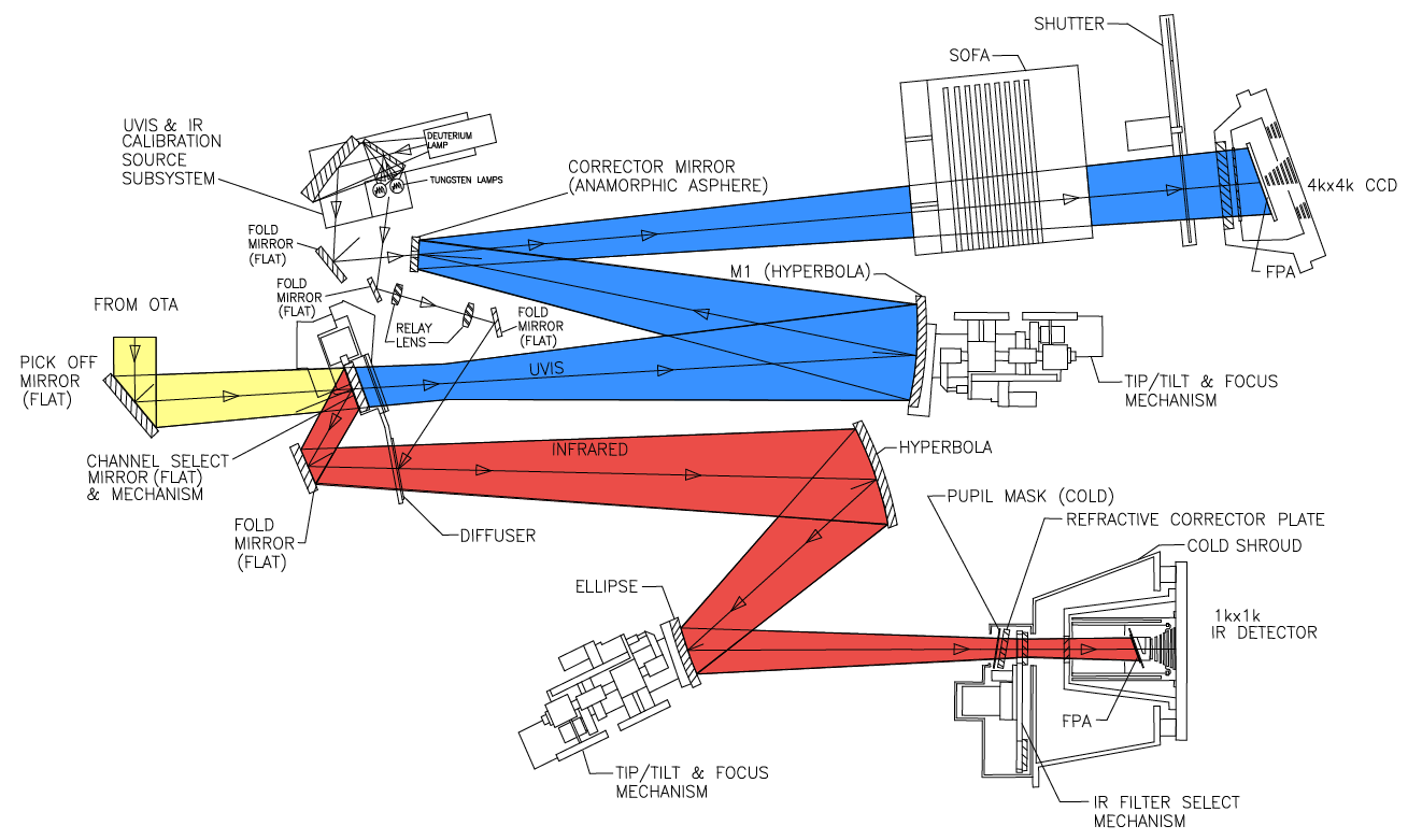
Table 2.1: Characteristics of the two WFC3 channels.
Channel | f-ratio | Detector | Spectral | Detector | Pixel scale | Field of view |
UVIS | 31 | CCD | 200-1000 | 2 × 2051 × 4096 | 0.0395 × 0.0395 | 162 × 162 |
IR | 11 | HgCdTe | 800-1700 | 1014 × 1014 | 0.135 × 0.121 | 136 × 123 |
-
WFC3 Instrument Handbook
- • Acknowledgments
- Chapter 1: Introduction to WFC3
- Chapter 2: WFC3 Instrument Description
- Chapter 3: Choosing the Optimum HST Instrument
- Chapter 4: Designing a Phase I WFC3 Proposal
- Chapter 5: WFC3 Detector Characteristics and Performance
-
Chapter 6: UVIS Imaging with WFC3
- • 6.1 WFC3 UVIS Imaging
- • 6.2 Specifying a UVIS Observation
- • 6.3 UVIS Channel Characteristics
- • 6.4 UVIS Field Geometry
- • 6.5 UVIS Spectral Elements
- • 6.6 UVIS Optical Performance
- • 6.7 UVIS Exposure and Readout
- • 6.8 UVIS Sensitivity
- • 6.9 Charge Transfer Efficiency
- • 6.10 Other Considerations for UVIS Imaging
- • 6.11 UVIS Observing Strategies
- Chapter 7: IR Imaging with WFC3
- Chapter 8: Slitless Spectroscopy with WFC3
-
Chapter 9: WFC3 Exposure-Time Calculation
- • 9.1 Overview
- • 9.2 The WFC3 Exposure Time Calculator - ETC
- • 9.3 Calculating Sensitivities from Tabulated Data
- • 9.4 Count Rates: Imaging
- • 9.5 Count Rates: Slitless Spectroscopy
- • 9.6 Estimating Exposure Times
- • 9.7 Sky Background
- • 9.8 Interstellar Extinction
- • 9.9 Exposure-Time Calculation Examples
- Chapter 10: Overheads and Orbit Time Determinations
-
Appendix A: WFC3 Filter Throughputs
- • A.1 Introduction
-
A.2 Throughputs and Signal-to-Noise Ratio Data
- • UVIS F200LP
- • UVIS F218W
- • UVIS F225W
- • UVIS F275W
- • UVIS F280N
- • UVIS F300X
- • UVIS F336W
- • UVIS F343N
- • UVIS F350LP
- • UVIS F373N
- • UVIS F390M
- • UVIS F390W
- • UVIS F395N
- • UVIS F410M
- • UVIS F438W
- • UVIS F467M
- • UVIS F469N
- • UVIS F475W
- • UVIS F475X
- • UVIS F487N
- • UVIS F502N
- • UVIS F547M
- • UVIS F555W
- • UVIS F600LP
- • UVIS F606W
- • UVIS F621M
- • UVIS F625W
- • UVIS F631N
- • UVIS F645N
- • UVIS F656N
- • UVIS F657N
- • UVIS F658N
- • UVIS F665N
- • UVIS F673N
- • UVIS F680N
- • UVIS F689M
- • UVIS F763M
- • UVIS F775W
- • UVIS F814W
- • UVIS F845M
- • UVIS F850LP
- • UVIS F953N
- • UVIS FQ232N
- • UVIS FQ243N
- • UVIS FQ378N
- • UVIS FQ387N
- • UVIS FQ422M
- • UVIS FQ436N
- • UVIS FQ437N
- • UVIS FQ492N
- • UVIS FQ508N
- • UVIS FQ575N
- • UVIS FQ619N
- • UVIS FQ634N
- • UVIS FQ672N
- • UVIS FQ674N
- • UVIS FQ727N
- • UVIS FQ750N
- • UVIS FQ889N
- • UVIS FQ906N
- • UVIS FQ924N
- • UVIS FQ937N
- • IR F098M
- • IR F105W
- • IR F110W
- • IR F125W
- • IR F126N
- • IR F127M
- • IR F128N
- • IR F130N
- • IR F132N
- • IR F139M
- • IR F140W
- • IR F153M
- • IR F160W
- • IR F164N
- • IR F167N
- Appendix B: Geometric Distortion
- Appendix C: Dithering and Mosaicking
- Appendix D: Bright-Object Constraints and Image Persistence
-
Appendix E: Reduction and Calibration of WFC3 Data
- • E.1 Overview
- • E.2 The STScI Reduction and Calibration Pipeline
- • E.3 The SMOV Calibration Plan
- • E.4 The Cycle 17 Calibration Plan
- • E.5 The Cycle 18 Calibration Plan
- • E.6 The Cycle 19 Calibration Plan
- • E.7 The Cycle 20 Calibration Plan
- • E.8 The Cycle 21 Calibration Plan
- • E.9 The Cycle 22 Calibration Plan
- • E.10 The Cycle 23 Calibration Plan
- • E.11 The Cycle 24 Calibration Plan
- • E.12 The Cycle 25 Calibration Plan
- • E.13 The Cycle 26 Calibration Plan
- • E.14 The Cycle 27 Calibration Plan
- • E.15 The Cycle 28 Calibration Plan
- • E.16 The Cycle 29 Calibration Plan
- • E.17 The Cycle 30 Calibration Plan
- • E.18 The Cycle 31 Calibration Plan
- • E.19 The Cycle 32 Calibration Plan
- • E.20 The Cycle 33 Calibration Plan
- • Glossary