5.6 WFC3 IR Readout Formats
5.6.1 Full-Frame Readouts and Reference Pixels
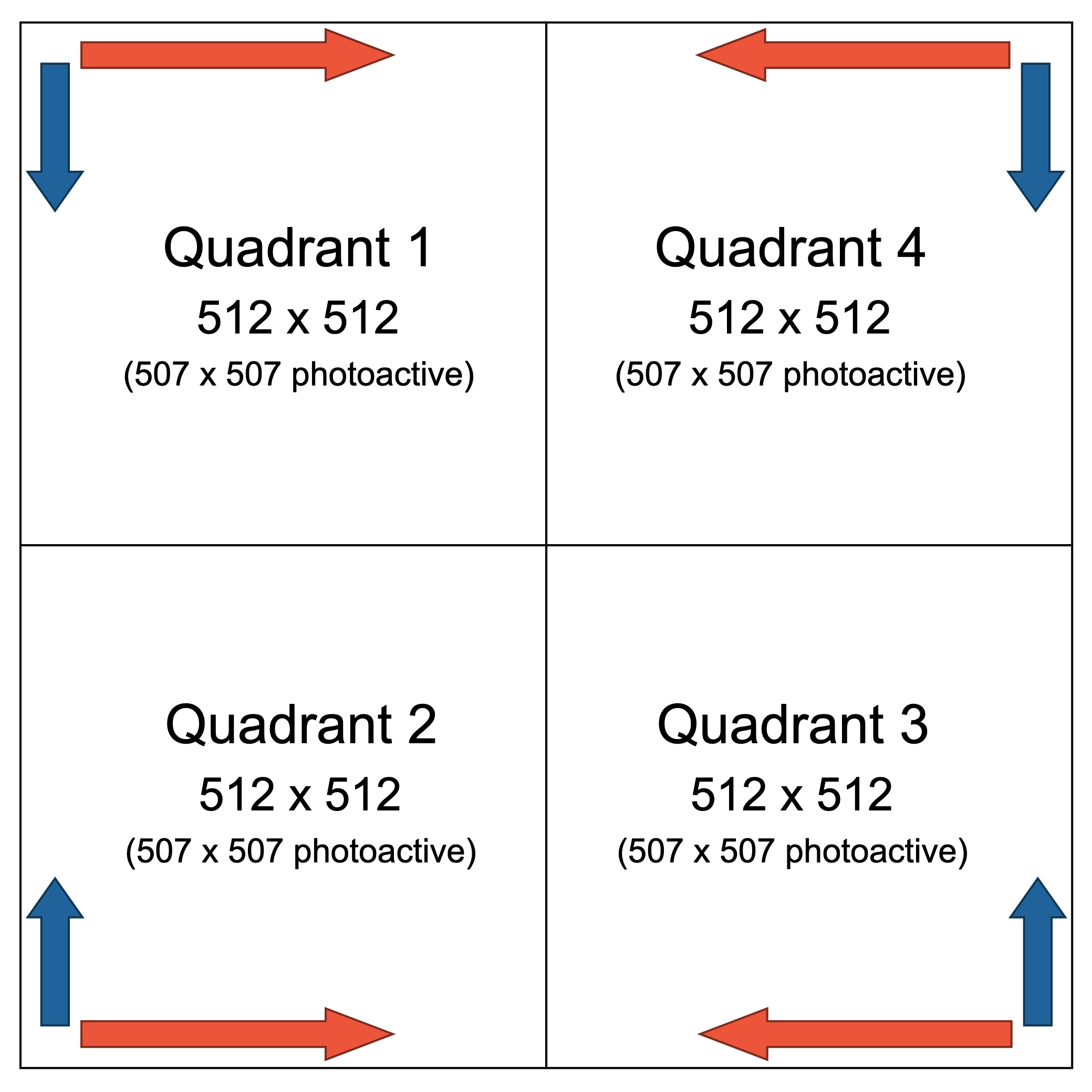
The WFC3 IR detector contains 1024 × 1024 square pixels of 18 × 18 micron physical size. The detector is divided into four quadrants of 512 × 512 pixels, each of which is read out independently from its outer corner, as illustrated in Figure 5.23. The outermost rows are read first, proceeding along each row from the outermost column to the horizontal mid-point of the detector, and then continuing inwards on subsequent rows to the vertical mid-point.
Figure 5.23: Schematic layout of the WFC3 IR detector. The long (red) and short (blue) arrows indicate the direction of the fast and slow multiplexer clocking, respectively. In contrast to CCD “bucket-brigade” image-shifting to the output amplifier, the IR detector pixels are selected for readout in a raster pattern by multiplexer circuits.
The reference pixels track the low-frequency drift of the readout electronics and efficiently remove the “pedestal” variations that affected, for example, NICMOS data. Analysis of ground test data has shown that the reference pixel signal is also sensitive to the detector temperature and may therefore be used to assess the expected level of dark current during an exposure, independently from a reading of the detector temperature itself. Actual on-orbit experience indicates that detector temperature is very stable.
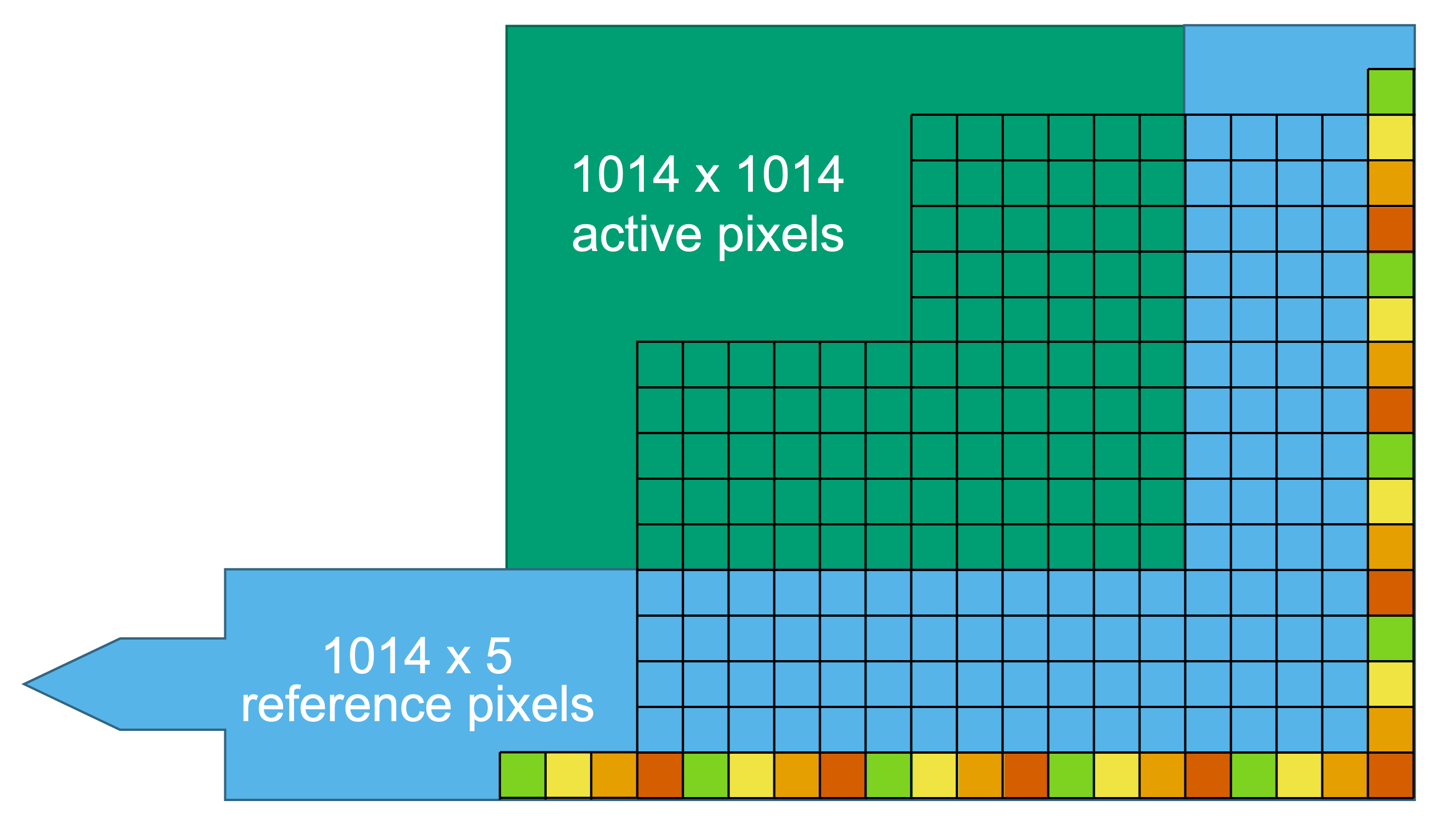
Full-frame exposures result in one raw 1024 × 1024 pixel image for each readout, which includes the 5 rows and columns of reference pixels on the periphery. After calibration, the reference pixels are trimmed off, leaving only the 1014 × 1014 arrays of light-gathering pixels.
Figure 5.24: Schematic layout of the light-sensitive pixels (dark green) and the reference pixels (light blue) at a corner of the WFC3/IR detector. The color-coding represents different values of the reference pixel capacitance.
5.6.2 Subarrays
The default IR exposure mode is to read out the entire detector. It is also possible, however, to read out only a portion of the detector. WFC3 IR subarrays are implemented in four user-selectable sizes: 64 × 64, 128 × 128, 256 × 256, and 512 × 512 pixels. All subarrays are centered on the detector with an equal number of pixels in each quadrant, using each of the 4 detector amplifiers to read the subarray pixels contained in its quadrant (as occurs with full-frame readouts).
The 5-pixel wide bands of reference pixels that share rows or columns with the subarray are also included in subarray readouts. The reference pixels therefore come from the same detector rows and columns as the “live” portion of the subarray, with the 5 × 5 pixels at the subarray corners filled by the reference pixels at the corresponding corner of the detector.
Certain sequences of IR subarrays and sample sequences give rise to images containing a sudden low-level jump in the overall background level of the image, an effect that can be avoided by ensuring observations are taken from largest to smallest, in that order. For more discussion of this as well as the use of IR subarrays, see Section 7.4.4.
-
WFC3 Instrument Handbook
- • Acknowledgments
- Chapter 1: Introduction to WFC3
- Chapter 2: WFC3 Instrument Description
- Chapter 3: Choosing the Optimum HST Instrument
- Chapter 4: Designing a Phase I WFC3 Proposal
- Chapter 5: WFC3 Detector Characteristics and Performance
-
Chapter 6: UVIS Imaging with WFC3
- • 6.1 WFC3 UVIS Imaging
- • 6.2 Specifying a UVIS Observation
- • 6.3 UVIS Channel Characteristics
- • 6.4 UVIS Field Geometry
- • 6.5 UVIS Spectral Elements
- • 6.6 UVIS Optical Performance
- • 6.7 UVIS Exposure and Readout
- • 6.8 UVIS Sensitivity
- • 6.9 Charge Transfer Efficiency
- • 6.10 Other Considerations for UVIS Imaging
- • 6.11 UVIS Observing Strategies
- Chapter 7: IR Imaging with WFC3
- Chapter 8: Slitless Spectroscopy with WFC3
-
Chapter 9: WFC3 Exposure-Time Calculation
- • 9.1 Overview
- • 9.2 The WFC3 Exposure Time Calculator - ETC
- • 9.3 Calculating Sensitivities from Tabulated Data
- • 9.4 Count Rates: Imaging
- • 9.5 Count Rates: Slitless Spectroscopy
- • 9.6 Estimating Exposure Times
- • 9.7 Sky Background
- • 9.8 Interstellar Extinction
- • 9.9 Exposure-Time Calculation Examples
- Chapter 10: Overheads and Orbit Time Determinations
-
Appendix A: WFC3 Filter Throughputs
- • A.1 Introduction
-
A.2 Throughputs and Signal-to-Noise Ratio Data
- • UVIS F200LP
- • UVIS F218W
- • UVIS F225W
- • UVIS F275W
- • UVIS F280N
- • UVIS F300X
- • UVIS F336W
- • UVIS F343N
- • UVIS F350LP
- • UVIS F373N
- • UVIS F390M
- • UVIS F390W
- • UVIS F395N
- • UVIS F410M
- • UVIS F438W
- • UVIS F467M
- • UVIS F469N
- • UVIS F475W
- • UVIS F475X
- • UVIS F487N
- • UVIS F502N
- • UVIS F547M
- • UVIS F555W
- • UVIS F600LP
- • UVIS F606W
- • UVIS F621M
- • UVIS F625W
- • UVIS F631N
- • UVIS F645N
- • UVIS F656N
- • UVIS F657N
- • UVIS F658N
- • UVIS F665N
- • UVIS F673N
- • UVIS F680N
- • UVIS F689M
- • UVIS F763M
- • UVIS F775W
- • UVIS F814W
- • UVIS F845M
- • UVIS F850LP
- • UVIS F953N
- • UVIS FQ232N
- • UVIS FQ243N
- • UVIS FQ378N
- • UVIS FQ387N
- • UVIS FQ422M
- • UVIS FQ436N
- • UVIS FQ437N
- • UVIS FQ492N
- • UVIS FQ508N
- • UVIS FQ575N
- • UVIS FQ619N
- • UVIS FQ634N
- • UVIS FQ672N
- • UVIS FQ674N
- • UVIS FQ727N
- • UVIS FQ750N
- • UVIS FQ889N
- • UVIS FQ906N
- • UVIS FQ924N
- • UVIS FQ937N
- • IR F098M
- • IR F105W
- • IR F110W
- • IR F125W
- • IR F126N
- • IR F127M
- • IR F128N
- • IR F130N
- • IR F132N
- • IR F139M
- • IR F140W
- • IR F153M
- • IR F160W
- • IR F164N
- • IR F167N
- Appendix B: Geometric Distortion
- Appendix C: Dithering and Mosaicking
- Appendix D: Bright-Object Constraints and Image Persistence
-
Appendix E: Reduction and Calibration of WFC3 Data
- • E.1 Overview
- • E.2 The STScI Reduction and Calibration Pipeline
- • E.3 The SMOV Calibration Plan
- • E.4 The Cycle 17 Calibration Plan
- • E.5 The Cycle 18 Calibration Plan
- • E.6 The Cycle 19 Calibration Plan
- • E.7 The Cycle 20 Calibration Plan
- • E.8 The Cycle 21 Calibration Plan
- • E.9 The Cycle 22 Calibration Plan
- • E.10 The Cycle 23 Calibration Plan
- • E.11 The Cycle 24 Calibration Plan
- • E.12 The Cycle 25 Calibration Plan
- • E.13 The Cycle 26 Calibration Plan
- • E.14 The Cycle 27 Calibration Plan
- • E.15 The Cycle 28 Calibration Plan
- • E.16 The Cycle 29 Calibration Plan
- • E.17 The Cycle 30 Calibration Plan
- • E.18 The Cycle 31 Calibration Plan
- • E.19 The Cycle 32 Calibration Plan
- • E.20 The Cycle 33 Calibration Plan
- • Glossary