7.5 IR Spectral Elements
7.5.1 Filter and Grism Summary
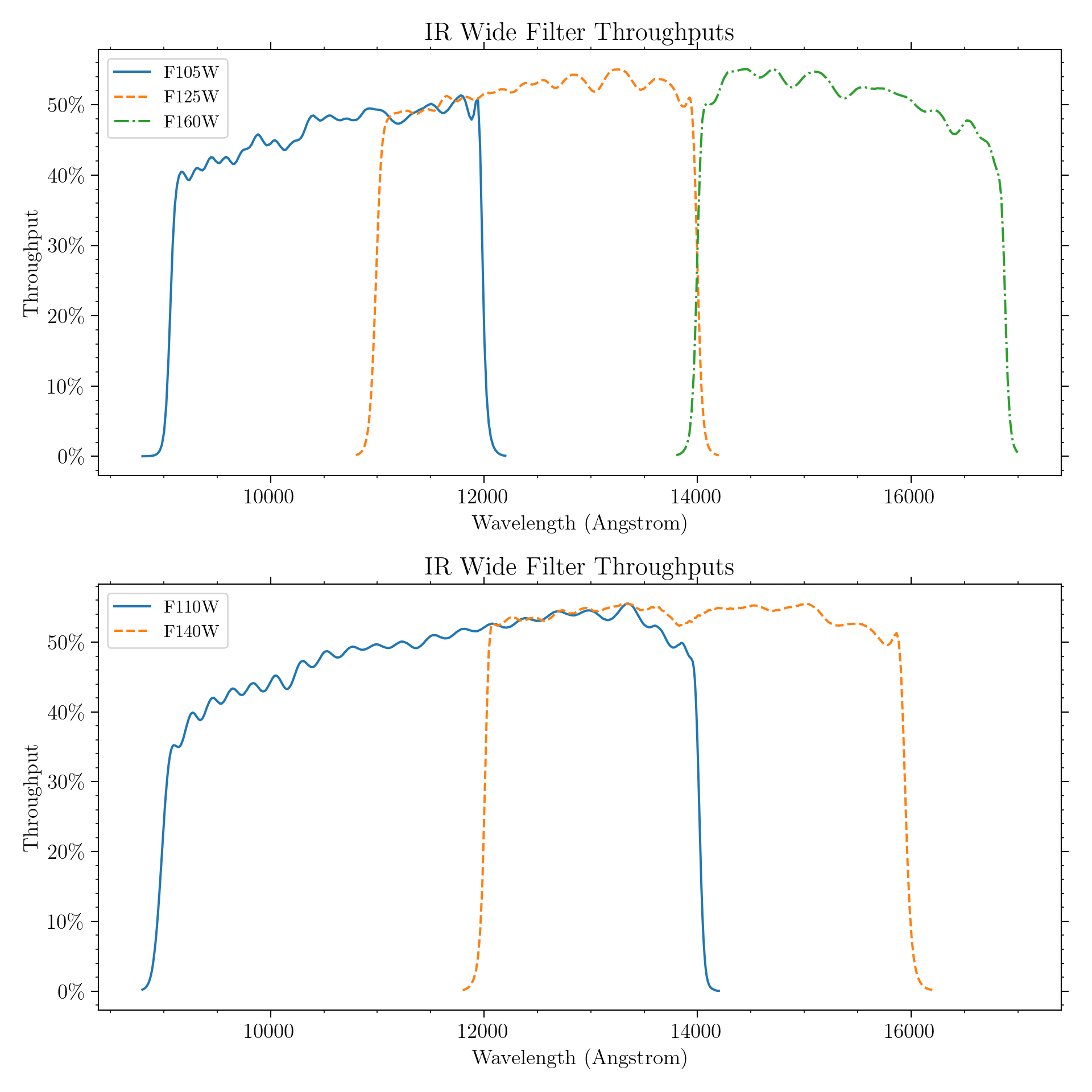
An overview of the IR spectral elements and of the process by which they were selected was given in Section 2.3. This section provides details of the IR filters and grisms. Table 7.2 lists the IR channel’s filters, with a general description and fundamental parameters of each. Figures 7.2, 7.3, and 7.4 show the effective throughput curves of the WFC3/IR wide, medium, and narrow filters, respectively, including the filter transmission multiplied by the throughput of the OTA, WFC3 optics, and detector response.
More information on the integrated system throughput curves for all of the filters is given in Appendix A; in particular, Section A.2.1 describes how to generate tabular versions of the throughput curves using synphot. All measurements of the IR filters which involve wavelengths, as tabulated in Table 7.2 and plotted in Figures 7.2, 7.3, and 7.4, respectively, and in Appendix A, were done in helium rather than vacuum. In addition, the laboratory measurements were performed at a temperature of –30°C, whereas on-orbit operating temperature of the filters is –35°C; this may lead to wavelength shifts which are expected to be very small.
The IR channel is equipped with a single filter wheel with 18 slots, containing 15 passband filters, two grisms, and an opaque element (also referred to as the BLANK) for dark current measurements. The filter complement samples the spectral region between 800 and 1700 nm. All of the IR filter elements are full-sized, covering the entire field of view of the IR detector. Since all of the elements are mounted in a single wheel, only one element can be used at a given time.
The 900–1700 nm wavelength range is covered by a series of wide- and medium-band filters, with little wavelength overlap. Additional medium-band filters are centered on molecular bands and nearby continua, and several narrow-band filters are available for probing interstellar and nebular recombination lines.
The filter set is designed to include the most popular passbands used in extragalactic, stellar, and solar-system astronomy, as well as passbands similar to those already used in previous HST instruments.
Table 7.2: WFC3 IR Channel Filters and Grisms.
Name1 | Description | Pivot2 λp | Width3 | Cumulative Throughput Width4 (nm) | Peak System Throughput |
IR Wide-Band (W) Filters | |||||
F105W | Wide Y | 1055.2 | 265.0 | 278.6 | 0.52 |
F110W | Wide YJ | 1153.4 | 443.0 | 475 | 0.56 |
F125W | Wide J | 1248.6 | 284.5 | 286.9 | 0.56 |
F140W | Wide JH gap; red grism reference | 1392.3 | 384.0 | 375.6 | 0.56 |
F160W | WFC3 H | 1536.9 | 268.3 | 273.6 | 0.56 |
IR Medium-Band (M) Filters | |||||
F098M | Blue grism reference | 986.4 | 157.0 | 163.1 | 0.47 |
F127M | H2O/CH4 continuum | 1274.0 | 68.8 | 69.9 | 0.54 |
F139M | H2O/CH4 line | 1383.8 | 64.3 | 65.6 | 0.54 |
F153M | H2O and NH3 | 1532.2 | 68.5 | 69.7 | 0.55 |
IR Narrow-Band (N) Filters | |||||
F126N | [Fe II] | 1258.5 | 15.2 | 15.5 | 0.50 |
F128N | Paschen β | 1283.2 | 15.9 | 16.3 | 0.52 |
F130N | Paschen β continuum | 1300.6 | 15.6 | 15.8 | 0.54 |
F132N | Paschen β (redshifted) | 1318.8 | 16.1 | 16.3 | 0.52 |
F164N | [Fe II] | 1640.4 | 20.9 | 21.0 | 0.47 |
F167N | [Fe II] continuum | 1664.2 | 21.0 | 21.4 | 0.46 |
IR Grisms (G) | |||||
G102 | “Blue” high-resolution grism | Useful range: 800–1150 nm5 | 0.41 | ||
G141 | “Red” low-resolution grism | Useful range: 1075–1700 nm5 | 0.48 | ||
1. See Footnote 1 of Table 6.2 for naming conventions.
2. “Pivot wavelength” is defined as in Table 6.2 and Section 9.3. Filter transmissions were measured in helium but have been converted to vacuum wavelengths for this table.
3. Passband rectangular width, defined as in Table 6.2.
4. Cumulative throughput width (CTW95), an alternate measure of bandwidth, is defined as the wavelength range which captures from 2.5% to 97.5% of the cumulative throughput of a filter.
5. See Chapter 8 for IR Grism details.
Wide-Band Filters
The IR channel’s versions of the ground-based J and H filters are F125W and F160W, respectively. The F125W filter has a width somewhat wider than that of a typical J passband used in ground-based cameras. The F160W filter’s bandpass has been modified relative to ground-based H in order to give a better fit to the QE curve of the IR detector. Specifically, the WFC3 H filter’s bandpass has been narrowed to approximately 1400-1700 nm, in order to limit thermal background and to have the filter define the bandpass on the red side rather than the detector sensitivity cutoff. By contrast, NICMOS H filter (NICMOS F160W) covers about 1400-1800 nm. This narrowing for WFC3 reduces photometric errors due to spatial variations in the detector’s QE cutoff.
The wide F140W filter covers the gap between the J and H bands that is inaccessible from the ground. F105W has a central wavelength similar to ground-based Y, but is considerably wider. The IR channel also includes a very wide filter, F110W, spanning the ground-based Y and J bands. This filter can be used for deep imaging, with a bandpass fairly similar to that of the corresponding wide-band filter in NICMOS (also called F110W).
Figure 7.2: Integrated system throughput of the WFC3 IR wide-band filters, presented in two panels for clarity. The throughput calculations include the HST OTA, WFC3 IR-channel internal throughput, filter transmittance, and the QE of the IR detector.
Medium-Band filters
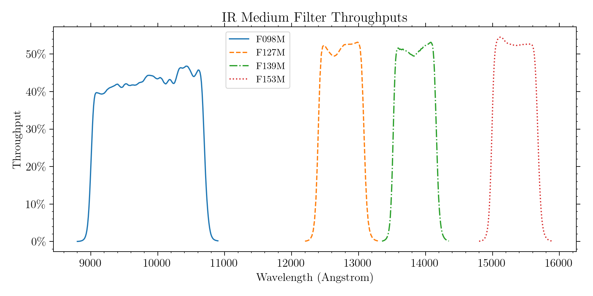
The F098M filter is useful as the G102 grism reference, allowing source selection and wavelength zero-point determination. It also complements the UVIS F845M filter, whose red 50% critical wavelength is ~900 nm. The overlap allows coverage over a continuous wavelength range across both WFC3 detectors.
The other medium filters span absorption bands of water and methane (F139M) and water and ammonia (F153M), with an adjacent continuum filter (F127M). These filters were intended for compositional studies of planets searching for water vapor (WFC3 ISR 2000-09). Solar system objects with visible inventories of these gas species are too bright to observe with the medium-band filters, and WFC3 lacks occulting hardware to access the high contrast ratios and small angular separations that would enable direct imaging of exoplanets. However, the high sensitivity of WFC3 enables compositional studies of the atmospheres of cool stars, brown dwarfs, and transiting exoplanets with the medium-band filters.
Figure 7.3: Integrated system throughput of the WFC3 IR medium-band filters. The throughput calculations include the HST OTA, WFC3 IR-channel internal throughput, filter transmittance, and the QE of the IR detector.
Narrow-Band Filters
The IR channel includes six narrow-band filters which sample some of the most astrophysically-important planetary, stellar, and nebular spectral features in the near-IR (e.g., [Fe II] and Paschen-β).
Cosmological emission lines can be detected across a range of redshifts within the bandpasses of the narrow-band filters. Table 7.3 lists the redshifts that can be probed using the specified emission lines. These redshift ranges are offered as a guide; exact values depend on the wavelengths of the filter cutoffs. Filter cutoffs used in Table 7.3 were defined using the passband rectangular widths (defined in footnote 4 of Table 6.2). For consistency with Table 6.2, passband cutoffs were not centered on the filter pivot wavelengths λp (defined in Section 9.3). Instead, a central wavelength for each filter was determined by maximizing the wavelength-integrated product of a rectangular passband of the specified width with the actual system throughput for the filter. For the IR narrow-band filters, these rectangular passband equivalent central wavelengths are within 0.3% of the pivot wavelengths.
Figure 7.4: Integrated system throughput of the WFC3 IR narrow-band filters. The throughput calculations include the HST OTA, WFC3 IR-channel internal throughput, filter transmittance, and the QE of the IR detector.
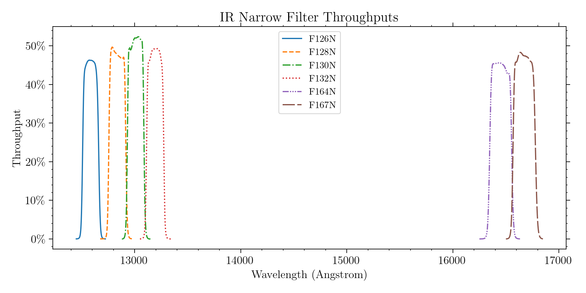
Table 7.3: Nominal redshift ranges for WFC3/IR narrow-band filters.
Filter | Description | Filter λp(nm) | Filter Width | Line Rest Wavelength (nm) | Minimum cz(km/sec) | Maximum cz(km/sec) |
F126N | [Fe II] on | 1258.5 | 15.2 | 1256.7 | -1312 | 2314 |
F128N | Pa β on or [Fe II] off | 1283.2 | 15.9 | 1281.8 | -1415 | 2304 |
F130N | z (Pa β) or Pa β off | 1300.6 | 15.6 | 1281.8 | 2690 | 6338 |
F132N | [Fe II] off or Pa β off | 1318.8 | 16.1 | |||
F164N | [Fe II] on | 1640.4 | 20.9 | 1643.6 | -1632 | 2180 |
F167N | [Fe II] off | 1664.2 | 21.0 | 1643.6 | 2371 | 6202 |
Grisms
The IR channel has two grisms that provide slitless spectra (see Chapter 8 for more details). The “blue” G102 grism provides a dispersion of 2.5 nm/pix (or a resolution of ~210) over the 800-1150 nm wavelength range. The “red” G141 grism has a dispersion of 4.7 nm/pix (resolution of ~130) over the 1100-1700 nm range. In most cases, a grism observation will be accompanied by a direct image, for source identification and wavelength calibration (see Section 8.3).
7.5.2 Filter Blue Leaks
All of the IR filters have been constructed using IR-transmitting colored glass with thin-film coatings to achieve the desired bandpasses. As with the UVIS filter designs, better in-band transmission generally means somewhat less suppression of out-of-band transmission. While the final IR filters have excellent in-band transmission (>90%), a few also have a small, narrow peak of transmission between 750-800 nm. After the filters were manufactured, a new IR detector was chosen which has appreciable sensitivity well down into the optical wavelength range (see Figure 5.25). Some of the IR filters thus have a small amount of blue leak (i.e., a small amount of short-wavelength out-of-band light is detected). None of the IR filters have significant red leaks.
Table 7.4 presents estimates of the blue-leak effect, listing the fraction of detected count rate expected from 710 to 830 nm for each filter. The throughput calculation includes transmission of the filter, the throughputs of the HST OTA and the IR optics, and the QE of the IR detector.
As can be seen from the table, blue leaks in all the wide-band and some of the narrow- and medium-band filters are minimal; however, several filters, notably F126N, F128N, and F153M, have some blue leak (e.g., ~1% for objects with effective temperatures of 5000 K.) In programs that may suffer adverse effects due to the blue leaks, it may be useful to obtain UVIS images in the F763M filter, which covers the problematic wavelength region (750-800 nm).
Table 7.4: Fraction of detected count rate arising between wavelengths 710 to 830 nm as a function of effective temperature.
Filter | Teff (K) | ||||||||||
3500 | 5000 | 10000 | 15000 | 20000 | 25000 | 30000 | 35000 | 40000 | 45000 | 50000 | |
F098M | 3.8E-05 | 6.1E-05 | 8.4E-05 | 9.3E-05 | 9.8E-05 | 1.0E-04 | 1.0E-04 | 1.1E-04 | 1.1E-04 | 1.1E-04 | 1.1E-04 |
F105W | 1.5E-05 | 2.2E-05 | 3.2E-05 | 3.5E-05 | 3.7E-05 | 3.9E-05 | 4.0E-05 | 4.1E-05 | 4.1E-05 | 4.1E-05 | 4.1E-05 |
F110W | 8.8E-08 | 1.4E-07 | 2.4E-07 | 2.7E-07 | 2.9E-07 | 3.0E-07 | 3.1E-07 | 3.2E-07 | 3.2E-07 | 3.2E-07 | 3.2E-07 |
F125W | 1.5E-07 | 2.4E-07 | 4.6E-07 | 5.3E-07 | 5.7E-07 | 6.1E-07 | 6.3E-07 | 6.5E-07 | 6.5E-07 | 6.5E-07 | 6.5E-07 |
F126N | 6.4E-03 | 1.3E-02 | 2.6E-02 | 3.0E-02 | 3.3E-02 | 3.5E-02 | 3.6E-02 | 3.7E-02 | 3.8E-02 | 3.8E-02 | 3.8E-02 |
F127M | 1.6E-03 | 3.2E-03 | 6.9E-03 | 8.0E-03 | 8.7E-03 | 9.2E-03 | 9.6E-03 | 9.8E-03 | 9.9E-03 | 1.0E-02 | 1.0E-02 |
F128N | 5.7E-03 | 1.2E-02 | 2.7E-02 | 3.1E-02 | 3.3E-02 | 3.5E-02 | 3.6E-02 | 3.7E-02 | 3.7E-02 | 3.7E-02 | 3.7E-02 |
F130N | 3.8E-04 | 6.7E-04 | 1.4E-03 | 1.6E-03 | 1.8E-03 | 1.9E-03 | 2.0E-03 | 2.0E-03 | 2.1E-03 | 2.1E-03 | 2.1E-03 |
F132N | 3.7E-04 | 6.6E-04 | 1.4E-03 | 1.7E-03 | 1.8E-03 | 1.9E-03 | 2.0E-03 | 2.1E-03 | 2.1E-03 | 2.1E-03 | 2.1E-03 |
F139M | 2.2E-03 | 3.9E-03 | 9.0E-03 | 1.1E-02 | 1.2E-02 | 1.3E-02 | 1.3E-02 | 1.4E-02 | 1.4E-02 | 1.4E-02 | 1.4E-02 |
F140W | 6.3E-05 | 1.0E-04 | 2.4E-04 | 2.9E-04 | 3.2E-04 | 3.4E-04 | 3.5E-04 | 3.7E-04 | 3.7E-04 | 3.7E-04 | 3.7E-04 |
F153M | 5.6E-03 | 9.9E-03 | 2.8E-02 | 3.3E-02 | 3.6E-02 | 3.9E-02 | 4.1E-02 | 4.2E-02 | 4.3E-02 | 4.3E-02 | 4.3E-02 |
F160W | 9.4E-05 | 1.7E-04 | 4.8E-04 | 5.7E-04 | 6.3E-04 | 6.8E-04 | 7.1E-04 | 7.4E-04 | 7.4E-04 | 7.5E-04 | 7.5E-04 |
F164N | 3.8E-03 | 8.0E-03 | 2.6E-02 | 3.1E-02 | 3.4E-02 | 3.7E-02 | 3.9E-02 | 4.0E-02 | 4.0E-02 | 4.1E-02 | 4.1E-02 |
F167N | 3.3E-03 | 7.0E-03 | 2.2E-02 | 2.7E-02 | 3.0E-02 | 3.2E-02 | 3.4E-02 | 3.6E-02 | 3.6E-02 | 3.6E-02 | 3.6E-02 |
7.5.3 Ghosts
No significant optical ghosts are present in the IR channel.
-
WFC3 Instrument Handbook
- • Acknowledgments
- Chapter 1: Introduction to WFC3
- Chapter 2: WFC3 Instrument Description
- Chapter 3: Choosing the Optimum HST Instrument
- Chapter 4: Designing a Phase I WFC3 Proposal
- Chapter 5: WFC3 Detector Characteristics and Performance
-
Chapter 6: UVIS Imaging with WFC3
- • 6.1 WFC3 UVIS Imaging
- • 6.2 Specifying a UVIS Observation
- • 6.3 UVIS Channel Characteristics
- • 6.4 UVIS Field Geometry
- • 6.5 UVIS Spectral Elements
- • 6.6 UVIS Optical Performance
- • 6.7 UVIS Exposure and Readout
- • 6.8 UVIS Sensitivity
- • 6.9 Charge Transfer Efficiency
- • 6.10 Other Considerations for UVIS Imaging
- • 6.11 UVIS Observing Strategies
- Chapter 7: IR Imaging with WFC3
- Chapter 8: Slitless Spectroscopy with WFC3
-
Chapter 9: WFC3 Exposure-Time Calculation
- • 9.1 Overview
- • 9.2 The WFC3 Exposure Time Calculator - ETC
- • 9.3 Calculating Sensitivities from Tabulated Data
- • 9.4 Count Rates: Imaging
- • 9.5 Count Rates: Slitless Spectroscopy
- • 9.6 Estimating Exposure Times
- • 9.7 Sky Background
- • 9.8 Interstellar Extinction
- • 9.9 Exposure-Time Calculation Examples
- Chapter 10: Overheads and Orbit Time Determinations
-
Appendix A: WFC3 Filter Throughputs
- • A.1 Introduction
-
A.2 Throughputs and Signal-to-Noise Ratio Data
- • UVIS F200LP
- • UVIS F218W
- • UVIS F225W
- • UVIS F275W
- • UVIS F280N
- • UVIS F300X
- • UVIS F336W
- • UVIS F343N
- • UVIS F350LP
- • UVIS F373N
- • UVIS F390M
- • UVIS F390W
- • UVIS F395N
- • UVIS F410M
- • UVIS F438W
- • UVIS F467M
- • UVIS F469N
- • UVIS F475W
- • UVIS F475X
- • UVIS F487N
- • UVIS F502N
- • UVIS F547M
- • UVIS F555W
- • UVIS F600LP
- • UVIS F606W
- • UVIS F621M
- • UVIS F625W
- • UVIS F631N
- • UVIS F645N
- • UVIS F656N
- • UVIS F657N
- • UVIS F658N
- • UVIS F665N
- • UVIS F673N
- • UVIS F680N
- • UVIS F689M
- • UVIS F763M
- • UVIS F775W
- • UVIS F814W
- • UVIS F845M
- • UVIS F850LP
- • UVIS F953N
- • UVIS FQ232N
- • UVIS FQ243N
- • UVIS FQ378N
- • UVIS FQ387N
- • UVIS FQ422M
- • UVIS FQ436N
- • UVIS FQ437N
- • UVIS FQ492N
- • UVIS FQ508N
- • UVIS FQ575N
- • UVIS FQ619N
- • UVIS FQ634N
- • UVIS FQ672N
- • UVIS FQ674N
- • UVIS FQ727N
- • UVIS FQ750N
- • UVIS FQ889N
- • UVIS FQ906N
- • UVIS FQ924N
- • UVIS FQ937N
- • IR F098M
- • IR F105W
- • IR F110W
- • IR F125W
- • IR F126N
- • IR F127M
- • IR F128N
- • IR F130N
- • IR F132N
- • IR F139M
- • IR F140W
- • IR F153M
- • IR F160W
- • IR F164N
- • IR F167N
- Appendix B: Geometric Distortion
- Appendix C: Dithering and Mosaicking
- Appendix D: Bright-Object Constraints and Image Persistence
-
Appendix E: Reduction and Calibration of WFC3 Data
- • E.1 Overview
- • E.2 The STScI Reduction and Calibration Pipeline
- • E.3 The SMOV Calibration Plan
- • E.4 The Cycle 17 Calibration Plan
- • E.5 The Cycle 18 Calibration Plan
- • E.6 The Cycle 19 Calibration Plan
- • E.7 The Cycle 20 Calibration Plan
- • E.8 The Cycle 21 Calibration Plan
- • E.9 The Cycle 22 Calibration Plan
- • E.10 The Cycle 23 Calibration Plan
- • E.11 The Cycle 24 Calibration Plan
- • E.12 The Cycle 25 Calibration Plan
- • E.13 The Cycle 26 Calibration Plan
- • E.14 The Cycle 27 Calibration Plan
- • E.15 The Cycle 28 Calibration Plan
- • E.16 The Cycle 29 Calibration Plan
- • E.17 The Cycle 30 Calibration Plan
- • E.18 The Cycle 31 Calibration Plan
- • E.19 The Cycle 32 Calibration Plan
- • E.20 The Cycle 33 Calibration Plan
- • Glossary