9.7 Sky Background
As noted in the previous section, the backgrounds from the sky and from the detector must be taken into account when calculating expected signal-to-noise ratios (SNRs) or exposure times.
Detector backgrounds (as well as read-out noise) for the CCDs and IR detector are discussed in Chapter 5. Background added to CCD exposures using the post-flash option is discussed in Section 6.9.2. This section deals with the sky backgrounds that can affect WFC3 observations.
The most important sources of sky background are:
- Earthshine (ES).
- Zodiacal light (ZL).
- Geocoronal emission (GC).
The background in counts e− s−1 pixel−1 for imaging observations can be computed as:
| B_{sky} = \int{ I_{\lambda} S_{\lambda} m_{x} m_{y} d \lambda } |
where:
- Iλ is the surface brightness of the sky background, in erg cm−2 s−1 Å−1 arcsec−2.
- Sλ is the point-source sensitivity for the imaging mode.
- mx and my are the plate scales in arcsec pixel−1 along orthogonal axes.
In the case of slitless spectroscopy, the image of the sky through a disperser is not uniform, because some wavelengths fall off the detector for regions of sky near the edge of the field of view. The regions of lower sky background will be strips at the long- and short-wavelength edges of the field of view; a UVIS grism spectrum is roughly 270 pixels long, while an IR grism spectrum is roughly 170 pixels long. The maximum width of the strips from where the signal starts to decline to the edge, where the signal is down by roughly a factor of 2, will be about half the total length of a spectrum of a point source, i.e., roughly 135 pixels (UVIS) or 85 pixels (IR), in the case of a sky background with a continuum of wavelengths. These small strips of lower sky background are ignored in the following formulae. Furthermore, since the spectra do not lie along the direction of the anamorphic distortion, the plate scales of mx and my above must be replaced by the plate scales ms and my in the orthogonal spatial and dispersion directions, respectively. Interior to the strips, a point on the detector sees a region of sky over the full wavelength coverage of the disperser. Thus, for spectroscopic observations:
| B^{\lambda}_{sky} = \int{ I_{\lambda} S'_{\lambda} m_{s} m_{\lambda} d\lambda } |
For a monochromatic sky emission line at λ = L like [O II] 2471, which will dominate the background through the UVIS/G280 grism:
| B^{L}_{sky} = I_{L} S'_{\lambda} m_{s} \frac{m_{\lambda}}{d} |
where
- IL is the monochromatic intensity of a line at wavelength L in erg cm−2 s−1 arcsec−2.
The total sky background is:
| B_{sky} = B^{\lambda}_{sky} + B^{L}_{sky} |
Figure 9.1 and Table 9.3 show "high" sky background intensity as a function of wavelength, identifying the separate components which contribute to the background. The "shadow" and "average" values of the earth-shine contribution in the WFC3 Exposure Time Calculator (ETC) correspond, respectively, to 0% and 50% of the "high" values in Figure 9.1 and Table 9.3. For the zodiacal sky background, the values in Figure 9.1 and Table 9.3 correspond to the high value of V-band surface brightness of 22.1 mag arcsec−2 from Table 9.4, while the "low" and "average" zodiacal light is scaled to V surface brightnesses of 23.3 and 22.7 mag arcsec−2, respectively.
In Table 9.3 we present the "high" sky-background numbers, which are plotted in Figure 9.1. See the text and the caption of Figure 9.1 for more details. These high sky values are defined as the earth-shine at 38° from the limb and the high zodiacal light of V = 22.1 mag arcsec−2.
Table 9.3: High Sky Backgrounds.
Wavelength | Earth-shine | Zodiacal light | Total sky background |
2000 | 7.69E-22 | 7.94E-20 | 8.02E-20 |
2500 | 1.53E-21 | 3.83E-19 | 3.84E-19 |
3000 | 1.43E-19 | 1.63E-18 | 1.77E-18 |
3500 | 8.33E-19 | 2.72E-18 | 3.55E-18 |
4000 | 1.66E-18 | 3.12E-18 | 4.78E-18 |
4500 | 2.59E-18 | 4.97E-18 | 7.57E-18 |
5000 | 2.63E-18 | 5.07E-18 | 7.70E-18 |
5500 | 2.55E-18 | 5.17E-18 | 7.72E-18 |
6000 | 2.42E-18 | 5.14E-18 | 7.56E-18 |
7000 | 1.95E-18 | 4.48E-18 | 6.42E-18 |
8000 | 1.56E-18 | 3.82E-18 | 5.38E-18 |
9000 | 1.23E-18 | 3.18E-18 | 4.40E-18 |
10000 | 9.97E-19 | 2.70E-18 | 3.70E-18 |
11000 | 8.02E-19 | 2.26E-18 | 3.06E-18 |
12000 | 6.65E-19 | 1.94E-18 | 2.61E-18 |
13000 | 5.58E-19 | 1.68E-18 | 2.24E-18 |
14000 | 4.70E-19 | 1.46E-18 | 1.93E-18 |
15000 | 3.97E-19 | 1.26E-18 | 1.66E-18 |
16000 | 3.35E-19 | 1.09E-18 | 1.43E-18 |
17000 | 2.79E-19 | 9.27E-19 | 1.21E-18 |
Figure 9.1: Sky background intensity as a function of wavelength.
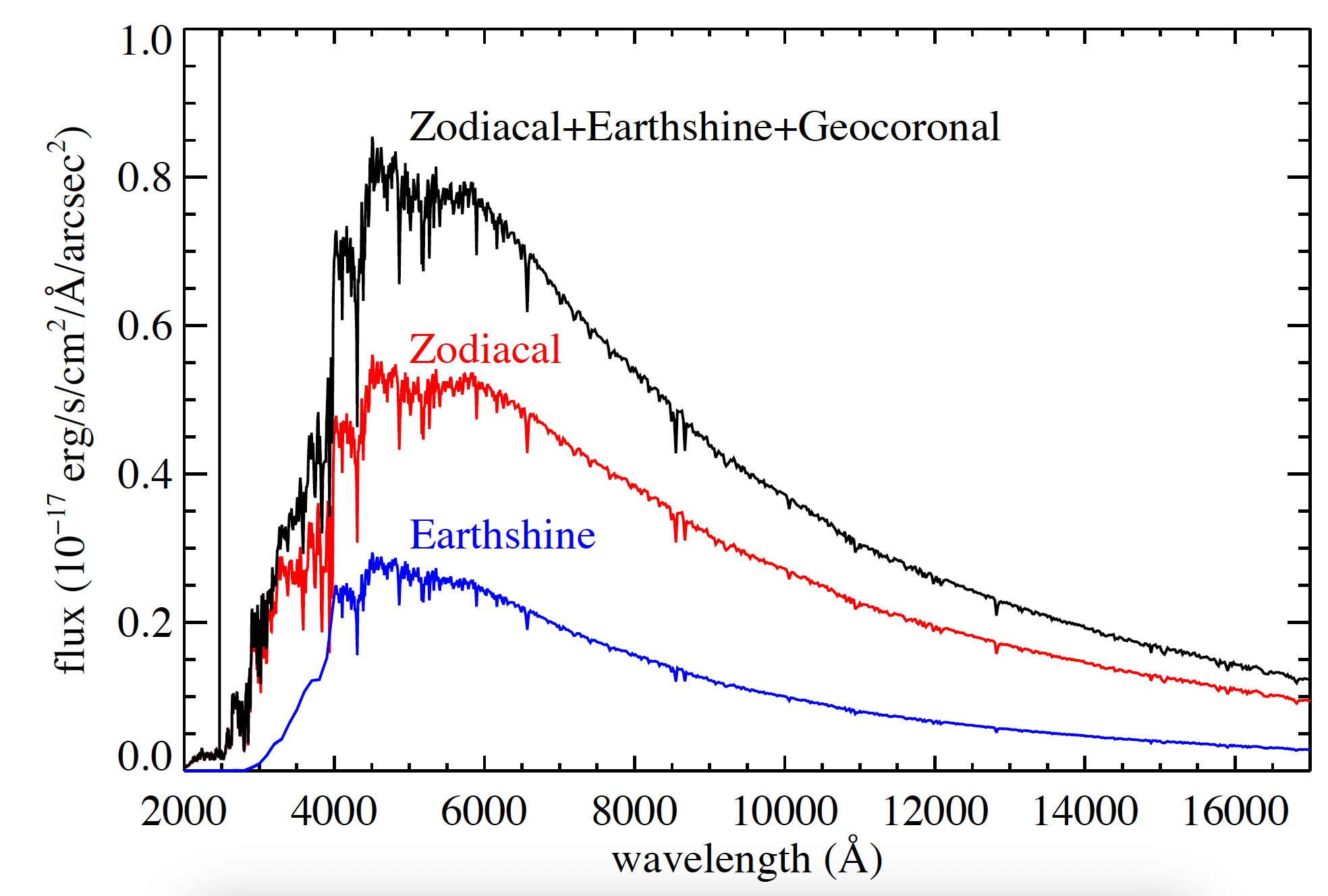
The total sky spectrum (black) for the "high-background" case adopted in the WFC3 ETC, along with the individual contributions from zodiacal light and earth-shine. These data correspond to a V-band surface brightness of 22.1 mag arcsec−2. The geocoronal emission line [O II] 2471 Å has a flux of 1.5 × 10⁻¹⁵ erg cm−2 s−1 arcsec−2, extending beyond the upper limit of the plot. See Section 7.9.5 for discussion of the He I emission line at 10830 Å, not plotted here.
9.7.1 Zodiacal Light, Earth Shine, and LOW-SKY
Zodiacal light varies as a function of angular distance of the target from the Sun and from the ecliptic. Table 9.4 gives the variation of the zodiacal background as a function of heliocentric ecliptic longitude and ecliptic latitude in V-mag per arcsec2. The entries in the table are derived from data in Leinert et al. (1998). As shown by this table, over most of the sky the zodiacal background is within 1 magnitude of the minimum value of 23.4 V-mag per arcsec2. It is greater than that at low ecliptic latitudes and at angles from the sun approaching the minimum permitted observing angle of 55°. At the lower ecliptic latitudes, it rises rapidly as this 55° limit is approached. For a target near heliocentric ecliptic coordinates (50,0) or (−50,0), not shown in the table, the zodiacal light level is 20.9 V-mag per arcsec2, i.e., about 10 times the faintest value. For an empirical determination of the dependence of zodiacal light on the ecliptic latitude and the angle between the target and the sun for WFC3/IR observations, see Section 7.9.5. Figure 7.12 illustrates this dependence.
Table 9.4: Approximate zodiacal sky background as a function of heliocentric ecliptic longitude and ecliptic latitude (in V-mag per arcsec2). SA stands for Solar Avoidance zone (HST pointing within 55 deg of the sun), where observations may not be made.
Ecliptic longitude (degrees) | Ecliptic latitude (degrees) | ||||||
0 | 15 | 30 | 45 | 60 | 75 | 90 | |
0 | SA | SA | SA | SA | 22.6 | 23.0 | 23.3 |
15 | SA | SA | SA | SA | 22.6 | 23.1 | 23.3 |
30 | SA | SA | SA | 22.3 | 22.7 | 23.1 | 23.3 |
45 | SA | SA | 22.1 | 22.5 | 22.9 | 23.1 | 23.3 |
60 | 21.3 | 21.9 | 22.4 | 22.7 | 23.0 | 23.2 | 23.3 |
75 | 21.7 | 22.2 | 22.6 | 22.9 | 23.1 | 23.2 | 23.3 |
90 | 22.0 | 22.3 | 22.7 | 23.0 | 23.2 | 23.3 | 23.3 |
105 | 22.2 | 22.5 | 22.9 | 23.1 | 23.3 | 23.3 | 23.3 |
120 | 22.4 | 22.6 | 22.9 | 23.2 | 23.3 | 23.3 | 23.3 |
135 | 22.4 | 22.6 | 22.9 | 23.2 | 23.3 | 23.4 | 23.3 |
150 | 22.4 | 22.6 | 22.9 | 23.1 | 23.3 | 23.4 | 23.3 |
165 | 22.3 | 22.5 | 22.8 | 23.0 | 23.2 | 23.4 | 23.3 |
180 | 22.1 | 22.4 | 22.7 | 23.0 | 23.2 | 23.4 | 23.3 |
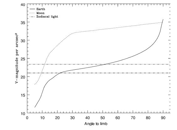
Earth-shine varies strongly depending on the angle between the target and the bright Earth limb. The variation of the earth-shine as a function of limb angle from the sunlit Earth is shown in Figure 9.2. The figure also shows the contribution of the moon, which is typically much smaller than the zodiacal contribution, for which the upper and lower limits are shown. For reference, the limb angle is approximately 24° when the HST is aligned toward its orbit pole (i.e., the center of the CVZ). The earth-shine contribution shown in Figure 9.1 and Table 9.3 corresponds to this position.
Figure 9.2: Background contributions in V magnitude per arcsec2 due to the zodiacal light, Moon, and sunlit Earth, as a function of angle between the target and the limb of the Earth or Moon. The two zodiacal light lines show the extremes of possible values.
Observations of the faintest objects may benefit from the use of the Phase II Special Requirement LOW-SKY, which must be requested and justified in the Phase I proposal. LOW-SKY observations are scheduled during the part of the year when the zodiacal background light is no more than 30% greater than the minimum possible zodiacal light for the given target position. LOW-SKY also invokes the restriction that exposures will be taken only at angles greater than 40° from the bright Earth limb to minimize earth-shine and the airglow lines (but also see Section 9.7.2). However it is not always effective in suppressing the He I 10830 Å airglow line (Section 7.9.5).
One disadvantage of using the LOW-SKY requirement is that it greatly reduces scheduling opportunities due to the restriction on zodiacal light. That restriction may be stricter than scientifically necessary, especially for targets at high ecliptic latitudes where even the maximum attainable zodiacal background is quite low, and for filters where other background components dominate the noise.
For targets and filters where high zodiacal background could be a problem, observers may want to limit that background by placing their own less stringent restrictions on scheduling dates to avoid observing the target when it is too near the sun. HST is already constrained to point at least 55° from the sun. For targets at low ecliptic latitude, that limit can be extended to ~60° by excluding 5 days from the ends of the default solar exclusion window, as described in Section 7.9.5.
Another disadvantage of using the LOW-SKY requirement is that it limits visibility to about 48 minutes per orbit. Rather than accept an automatic reduction in observing time by using LOW-SKY, the observer may be able to structure an orbit so that the exposures that would be most significantly affected by earth-shine do not occur at the beginning or end of the orbit, where the earth-shine is likely to be highest. The exposures in that orbit should be placed in a non-interruptible exposure sequence, as described in the APT Training Materials. For WFC3/IR exposures, frames in the non-destructive readouts that are badly affected by earth-shine can be excluded from the data reduction (see Section 7.9.5).
WFC3/UVIS observers should keep in mind that the total background (dark + sky + post-flash if needed) must be at least 20 electrons/pix/s to minimize CTE losses, so for some targets and filters it may be advisable to increase the background using post-flash rather than to attempt to minimize it (Section 6.9).
The ETC provides the user with the flexibility to separately adjust the zodiacal and earth-shine sky background component levels to help observers decide where special care is needed to avoid background levels that could be detrimental to their science. The RA, Dec and date option can be used to compute the zodiacal light for specific targets, which is especially useful for targets at low ecliptic latitudes where the zodiacal background increases rapidly as the angle between the target and the sun approaches the HST observable limit of 55°. Note that the standard normalizations for zodiacal light and earth-shine (from none to high or extremely high) provide approximations that may not accurately predict the levels in individual exposures. For WFC3/IR exposures, one can check the empirically determined zodiacal light model discussed in Section 7.9.5.
9.7.2 Geocoronal Emission, Airglow, and SHADOW
Background due to geocoronal emission originates mainly from hydrogen and oxygen atoms in the exosphere of the Earth. In the far-UV spectral region, the strongest geocoronal emission lines are Lyman−α at 1216 Å, O I at 1304 Å, and O I] at 1356 Å, but WFC3 is of course not sensitive at these wavelengths. The only significant UV geocoronal emission line to which WFC3 is sensitive is [O II] 2471 Å, shown in Figure 9.1. This line varies in intensity from day to night and as a function of HST orbital position. It can be the dominant sky contribution in the UV both for imaging and spectroscopic observations. In sunlight it can be as bright as ~1.5 × 10⁻¹⁵ erg cm−2 s−1 arcsec−2, while in Earth shadow it is much fainter, typically ~7.5 × 10⁻¹⁸ erg cm−2 s−1 arcsec−2. However, note that WFC3 ISR 2023-06 did not find any contribution attributable to [O II] to the G280 grism sky background.
To minimize geocoronal emission, the Special Requirement SHADOW can be used if requested and justified in the Phase I proposal. Exposures using this special requirement are limited to roughly 25 minutes per orbit, exclusive of the guide-star acquisition (or re-acquisition), and can be scheduled only during a small percentage of the year. SHADOW therefore restricts scheduling opportunities and orbit duration much more severely than LOW-SKY (see Section 7.9.1). SHADOW reduces the contribution from the geocoronal emission lines by roughly a factor of ten while the continuum earth-shine is set to zero. SHADOW requirements must be included and justified in your Phase I proposal (see the Call for Proposals). Observers should keep in mind that the total background should be at least 20 electrons/pix/s to minimize CTE losses in WFC3/UVIS images, so it may be advisable to increase the background using post-flash rather than to attempt to minimize it. (See Section 6.9)
Analysis of archival WFC3/IR grism and broad-band filter observations has shown that a variable airglow line of He I at 10830 Å can be a significant component of the sky background for the F105W and F110W filters and the G102 and G141 grisms. See Section 7.9.5 for discussion of the WFC3/IR sky background and observing strategies. The use of SHADOW is generally not recommended for WFC3/IR exposures.
-
WFC3 Instrument Handbook
- • Acknowledgments
- Chapter 1: Introduction to WFC3
- Chapter 2: WFC3 Instrument Description
- Chapter 3: Choosing the Optimum HST Instrument
- Chapter 4: Designing a Phase I WFC3 Proposal
- Chapter 5: WFC3 Detector Characteristics and Performance
-
Chapter 6: UVIS Imaging with WFC3
- • 6.1 WFC3 UVIS Imaging
- • 6.2 Specifying a UVIS Observation
- • 6.3 UVIS Channel Characteristics
- • 6.4 UVIS Field Geometry
- • 6.5 UVIS Spectral Elements
- • 6.6 UVIS Optical Performance
- • 6.7 UVIS Exposure and Readout
- • 6.8 UVIS Sensitivity
- • 6.9 Charge Transfer Efficiency
- • 6.10 Other Considerations for UVIS Imaging
- • 6.11 UVIS Observing Strategies
- Chapter 7: IR Imaging with WFC3
- Chapter 8: Slitless Spectroscopy with WFC3
-
Chapter 9: WFC3 Exposure-Time Calculation
- • 9.1 Overview
- • 9.2 The WFC3 Exposure Time Calculator - ETC
- • 9.3 Calculating Sensitivities from Tabulated Data
- • 9.4 Count Rates: Imaging
- • 9.5 Count Rates: Slitless Spectroscopy
- • 9.6 Estimating Exposure Times
- • 9.7 Sky Background
- • 9.8 Interstellar Extinction
- • 9.9 Exposure-Time Calculation Examples
- Chapter 10: Overheads and Orbit Time Determinations
-
Appendix A: WFC3 Filter Throughputs
- • A.1 Introduction
-
A.2 Throughputs and Signal-to-Noise Ratio Data
- • UVIS F200LP
- • UVIS F218W
- • UVIS F225W
- • UVIS F275W
- • UVIS F280N
- • UVIS F300X
- • UVIS F336W
- • UVIS F343N
- • UVIS F350LP
- • UVIS F373N
- • UVIS F390M
- • UVIS F390W
- • UVIS F395N
- • UVIS F410M
- • UVIS F438W
- • UVIS F467M
- • UVIS F469N
- • UVIS F475W
- • UVIS F475X
- • UVIS F487N
- • UVIS F502N
- • UVIS F547M
- • UVIS F555W
- • UVIS F600LP
- • UVIS F606W
- • UVIS F621M
- • UVIS F625W
- • UVIS F631N
- • UVIS F645N
- • UVIS F656N
- • UVIS F657N
- • UVIS F658N
- • UVIS F665N
- • UVIS F673N
- • UVIS F680N
- • UVIS F689M
- • UVIS F763M
- • UVIS F775W
- • UVIS F814W
- • UVIS F845M
- • UVIS F850LP
- • UVIS F953N
- • UVIS FQ232N
- • UVIS FQ243N
- • UVIS FQ378N
- • UVIS FQ387N
- • UVIS FQ422M
- • UVIS FQ436N
- • UVIS FQ437N
- • UVIS FQ492N
- • UVIS FQ508N
- • UVIS FQ575N
- • UVIS FQ619N
- • UVIS FQ634N
- • UVIS FQ672N
- • UVIS FQ674N
- • UVIS FQ727N
- • UVIS FQ750N
- • UVIS FQ889N
- • UVIS FQ906N
- • UVIS FQ924N
- • UVIS FQ937N
- • IR F098M
- • IR F105W
- • IR F110W
- • IR F125W
- • IR F126N
- • IR F127M
- • IR F128N
- • IR F130N
- • IR F132N
- • IR F139M
- • IR F140W
- • IR F153M
- • IR F160W
- • IR F164N
- • IR F167N
- Appendix B: Geometric Distortion
- Appendix C: Dithering and Mosaicking
- Appendix D: Bright-Object Constraints and Image Persistence
-
Appendix E: Reduction and Calibration of WFC3 Data
- • E.1 Overview
- • E.2 The STScI Reduction and Calibration Pipeline
- • E.3 The SMOV Calibration Plan
- • E.4 The Cycle 17 Calibration Plan
- • E.5 The Cycle 18 Calibration Plan
- • E.6 The Cycle 19 Calibration Plan
- • E.7 The Cycle 20 Calibration Plan
- • E.8 The Cycle 21 Calibration Plan
- • E.9 The Cycle 22 Calibration Plan
- • E.10 The Cycle 23 Calibration Plan
- • E.11 The Cycle 24 Calibration Plan
- • E.12 The Cycle 25 Calibration Plan
- • E.13 The Cycle 26 Calibration Plan
- • E.14 The Cycle 27 Calibration Plan
- • E.15 The Cycle 28 Calibration Plan
- • E.16 The Cycle 29 Calibration Plan
- • E.17 The Cycle 30 Calibration Plan
- • E.18 The Cycle 31 Calibration Plan
- • E.19 The Cycle 32 Calibration Plan
- • E.20 The Cycle 33 Calibration Plan
- • Glossary