6.7 UVIS Exposure and Readout
6.7.1 Exposure Time
Exposure times in the UVIS channel are controlled by a rotating mechanical shutter blade (see Section 2.3.3). The time per UVIS exposure must be between 0.5 s and 3600 s, excluding 0.6 s, in steps of 0.1 s.1 Early on-orbit observations revealed a slight, repeatable offset between the commanded and actual times for the two shortest exposures (0.5 s is 0.48 s and 0.7 s is 0.695 s); the data processing pipeline populates the EXPTIME header keyword with the actual exposure times. The repeatability of the shutter has been shown to be well within the contractual specifications of 10 ms r.m.s. (WFC3 ISR 2023-04). That analysis, based on short G280 exposures of a very bright star, allowed for substantially more precise measure of the repeatability than earlier measurements based on internal flat fields. In particular, the repeatablity of 0.5s, 0.7s, and > 0.99s exposures have been shown to be ~10x, ~2x, and ~4x better, respectively, than required by the specification. A Gaussian fit to the measured repeatability of 1, 2, and 4s exposures yields an r.m.s. of 2.43 ms +/-0.32 ms. Observers performing precise non-differential photometry using short exposures should note that, although well within operational specifications, the shutter repeatability in 1-s exposures contributes ~0.24% photometric error (WFC3 ISR 2023-04). In addition, note that the point spread function can be affected by shutter-induced vibration in short (< 5s) exposures; see Section 6.10.4.
The shutter uniformity requirement specifies that any differences in exposure time across the field of view must be < 0.01 s. Comparisons of long (30 s) and short (0.5 s) exposures taken during instrument-level ground tests have shown that the shutter provides a uniform exposure time across the field of view to ~0.004 s, easily meeting the requirement. In on-orbit internal tungsten lamp exposures, the exposure time across the field was found to vary by less than 0.0009 sec (WFC3 ISR 2009-25). Based on tungsten lamp exposures and observations of a standard star made from Oct. 2014 to Aug. 2015, no noticeable change in on-orbit shutter performance since launch was detected (WFC3 ISR 2015-12).
To allow for cosmic-ray removal during post-observation data processing, UVIS exposures can be split into multiple subexposures. The preferred method of removing cosmic rays is to combine dithered subexposures (see Section 6.11.1). As a result, the default value of CR-SPLIT in APT (to take undithered images) was changed from 2 to NO in 2010 (Cycle 18). In the rare case that undithered observations are required, setting CR-SPLIT to a value will divide the specified exposure time by the requested number of subexposures, with the subexposure times rounded down to the nearest multiple of 0.1 s. At the end of this process, if the resulting subexposure times are not legal values, the APT proposal software adjusts them so that they are allowed and reports those changes to the observer.
6.7.2 ACCUM Mode
“ACCUM” is the only observing mode for the UVIS channel. In ACCUM mode, the shutter is opened immediately after a CCD reset and photons strike the CCDs and generate charge, which is accumulated until the shutter is closed at the end of the requested exposure time and the charge is read out. During the readout, the analog-to-digital (A-to-D) converter translates the charge into data numbers (DN) via the gain setting. There are four possible gain settings (1.0, 1.5, 2.0, and 4.0 e–/DN) in principle; however, the only setting offered to observers is the default setting of 1.5 e–/DN, which provides an absolute gain of ~1.55 e–/DN (Table 5.1).
A full detector readout of both UVIS chips takes 96 s. The image contains all the exposed pixels from each CCD (2 times 2051 × 4096), as well as a variety of overscan pixels, described in more detail later in this section. Shorter readout times are possible by using smaller subarray readout sizes, as discussed in more detail in Section 6.4.4.
Each of the two CCD chips contains two on-chip amplifiers used for reading out. The fastest—and default—way to read out the entire detector, at full spatial resolution, is to use all four amplifiers simultaneously. Other full-detector readout modes are possible but take more time and involve more charge transfer shifts that will degrade the CTE. For example, two amplifier full frame readout takes more than twice as long as a four-amplifier readout (~193 s vs. 96 s). Non-default readout modes are not offered to General Observers.
Subarray frames, unlike full detector frames, are always read out by a single amplifier (the closest amplifier to the subarray center).
Overscan Regions
The UVIS CCD detectors each have 4096 × 2051 pixels that are exposed to light. In addition, both chips have 25 extra columns at both ends that are not exposed to light; these 25 columns are physical overscan pixels. Moreover, during readout of the chips, extra pixels can be clocked in order to create virtual overscan pixels.
The location of the overscan regions in a raw image varies, depending upon the type of readout that is performed. The overscan regions are used to monitor the instrument, and are needed to measure the bias level. The bias level is subtracted from the raw image, normally through the BLEVCORR step in the WFC3 calibration pipeline (see the WFC3 Data Handbook).
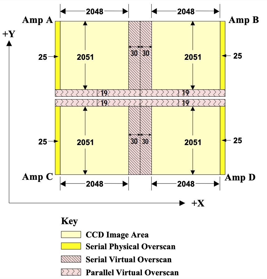
Figure 6.20 shows the format of a raw image obtained with full-chip unbinned four-amplifier readout; dimensions are also tabulated in Table 6.9. The raw image has 25 columns of physical overscan pixels and two areas of virtual overscan: 60 columns of serial overscan in the center of each row and 38 rows (19 per chip) of parallel overscan next to the inter-chip gap. The serial physical overscan pixels are also known as the serial prescan, or leading-edge, overscan; the serial virtual overscan pixels are also called the trailing-edge pixels.
Figure 6.20: Format of a Raw Full-Chip WFC3/UVIS image.
Exposures taken with on-chip binning are complicated by the need to truncate “odd” pixels and to treat each half of the chip’s row separately. Also, due to the odd number of some overscan pixels, the boundary between the data and overscan pixels of a binned exposure can contain binned pixels resulting from a combination of both data and overscan pixels. A 2 × 2 binned frame readout, for example, contains 2102 columns × 2070 rows. That is, each binned chip readout contains 2102 columns (12 physical overscan + 1 combined data/overscan + 1023 columns of data + 1 combined data/virtual overscan column + 14 virtual overscan pixels for each of the two amps in a chip), and each binned chip readout has 1035 rows (9 binned virtual overscan + 1 combined data/virtual parallel overscan + 1025 data). A 3 × 3 binned image contains 1402 × 1380 pixels (8 overscan + 1 combined overscan/data + 682 data + 10 overscan columns in each amplifier of each chip and 6 overscan + 1 combined overscan/data + 683 data rows in each chip). These values, as well as the dimensions for unbinned full-frame exposures, are also presented in Table 6.9.
Table 6.9: Dimensions of unbinned (1 × 1) and binned (2 × 2 and 3 × 3) WFC3/UVIS exposures. Full readout size is given, and the number of columns and rows by type (science, overscan, etc.) are listed.
| Columns | Rows | ||||||||
|---|---|---|---|---|---|---|---|---|---|
| Binning | Readout Size | Science | Serial physical overscan | Mixed (data/serial physical overscan) | Serial virtual overscan | Mixed (data/serial virtual overscan) | Science | Parallel virtual overscan | Mixed (data/virtual parallel overscan) |
| 1 × 1 | 4206 × 4140 | 4096 | 50 (25 per amp) | 60 (30 per amp) | 4102 (2051 per chip) | 38 (19 per chip) | |||
| 2 × 2 | 2102 × 2070 | 2046 | 24 (12 per amp) | 2 (1 per amp) | 28 (14 per amp) | 2 (1 per amp) | 2050 (1025 per chip) | 18 (9 per chip) | 2 (1 per chip) |
| 3 × 3 | 1402 × 1380 | 1364 | 16 (8 per amp) | 2 (1 per amp) | 20 (10 per amp) | 1366 (683 per chip) | 12 (6 per chip) | 2 (1 per chip) | |
For completeness, we mention here that WFC3 can also be commanded to take EPER (extended pixel edge response) readouts. This capability is intended for calibration/engineering purposes only. The EPER images are a way to measure and monitor charge transfer inefficiency (CTI) effects using internal images, rather than external, pointed observations that would take HST observing time away from science observations. The EPER frame starts with an internal tungsten lamp flat field; any CTI present causes a fraction of charge from that flat field to be captured temporarily in traps. As the frame is read out, the trapped charge escapes and can appear in the overscan regions as an exponential tail of deferred charge. The EPER readout includes significantly larger areas of overscan so that the full extent of the exponential tail can be measured, ideally down to where it becomes indistinguishable from the nominal noise level of the detector. That is, the EPER image allows direct measurement of the charge losses during the readout since all the lost electrons are expected to appear in the exponential tail. WFC3 ISR 2020-06 summarizes the EPER results based on 2009-2020 data, with updated results through 2025 summarized in WFC3 ISR 2025-02.
1 Under normal shutter operations, the 0.5 s exposure would not provide a sufficiently uniform exposure level. Thus, the shutter operation for 0.5 s has been implemented through a special “continuous sweep” operation, where the shutter disk moves smoothly through 180°, from one closed position to the next, thus meeting the uniformity requirement. All exposures longer than 0.5 s are obtained via pairs of closed-to-open and open-to-closed commands.
-
WFC3 Instrument Handbook
- • Acknowledgments
- Chapter 1: Introduction to WFC3
- Chapter 2: WFC3 Instrument Description
- Chapter 3: Choosing the Optimum HST Instrument
- Chapter 4: Designing a Phase I WFC3 Proposal
- Chapter 5: WFC3 Detector Characteristics and Performance
-
Chapter 6: UVIS Imaging with WFC3
- • 6.1 WFC3 UVIS Imaging
- • 6.2 Specifying a UVIS Observation
- • 6.3 UVIS Channel Characteristics
- • 6.4 UVIS Field Geometry
- • 6.5 UVIS Spectral Elements
- • 6.6 UVIS Optical Performance
- • 6.7 UVIS Exposure and Readout
- • 6.8 UVIS Sensitivity
- • 6.9 Charge Transfer Efficiency
- • 6.10 Other Considerations for UVIS Imaging
- • 6.11 UVIS Observing Strategies
- Chapter 7: IR Imaging with WFC3
- Chapter 8: Slitless Spectroscopy with WFC3
-
Chapter 9: WFC3 Exposure-Time Calculation
- • 9.1 Overview
- • 9.2 The WFC3 Exposure Time Calculator - ETC
- • 9.3 Calculating Sensitivities from Tabulated Data
- • 9.4 Count Rates: Imaging
- • 9.5 Count Rates: Slitless Spectroscopy
- • 9.6 Estimating Exposure Times
- • 9.7 Sky Background
- • 9.8 Interstellar Extinction
- • 9.9 Exposure-Time Calculation Examples
- Chapter 10: Overheads and Orbit Time Determinations
-
Appendix A: WFC3 Filter Throughputs
- • A.1 Introduction
-
A.2 Throughputs and Signal-to-Noise Ratio Data
- • UVIS F200LP
- • UVIS F218W
- • UVIS F225W
- • UVIS F275W
- • UVIS F280N
- • UVIS F300X
- • UVIS F336W
- • UVIS F343N
- • UVIS F350LP
- • UVIS F373N
- • UVIS F390M
- • UVIS F390W
- • UVIS F395N
- • UVIS F410M
- • UVIS F438W
- • UVIS F467M
- • UVIS F469N
- • UVIS F475W
- • UVIS F475X
- • UVIS F487N
- • UVIS F502N
- • UVIS F547M
- • UVIS F555W
- • UVIS F600LP
- • UVIS F606W
- • UVIS F621M
- • UVIS F625W
- • UVIS F631N
- • UVIS F645N
- • UVIS F656N
- • UVIS F657N
- • UVIS F658N
- • UVIS F665N
- • UVIS F673N
- • UVIS F680N
- • UVIS F689M
- • UVIS F763M
- • UVIS F775W
- • UVIS F814W
- • UVIS F845M
- • UVIS F850LP
- • UVIS F953N
- • UVIS FQ232N
- • UVIS FQ243N
- • UVIS FQ378N
- • UVIS FQ387N
- • UVIS FQ422M
- • UVIS FQ436N
- • UVIS FQ437N
- • UVIS FQ492N
- • UVIS FQ508N
- • UVIS FQ575N
- • UVIS FQ619N
- • UVIS FQ634N
- • UVIS FQ672N
- • UVIS FQ674N
- • UVIS FQ727N
- • UVIS FQ750N
- • UVIS FQ889N
- • UVIS FQ906N
- • UVIS FQ924N
- • UVIS FQ937N
- • IR F098M
- • IR F105W
- • IR F110W
- • IR F125W
- • IR F126N
- • IR F127M
- • IR F128N
- • IR F130N
- • IR F132N
- • IR F139M
- • IR F140W
- • IR F153M
- • IR F160W
- • IR F164N
- • IR F167N
- Appendix B: Geometric Distortion
- Appendix C: Dithering and Mosaicking
- Appendix D: Bright-Object Constraints and Image Persistence
-
Appendix E: Reduction and Calibration of WFC3 Data
- • E.1 Overview
- • E.2 The STScI Reduction and Calibration Pipeline
- • E.3 The SMOV Calibration Plan
- • E.4 The Cycle 17 Calibration Plan
- • E.5 The Cycle 18 Calibration Plan
- • E.6 The Cycle 19 Calibration Plan
- • E.7 The Cycle 20 Calibration Plan
- • E.8 The Cycle 21 Calibration Plan
- • E.9 The Cycle 22 Calibration Plan
- • E.10 The Cycle 23 Calibration Plan
- • E.11 The Cycle 24 Calibration Plan
- • E.12 The Cycle 25 Calibration Plan
- • E.13 The Cycle 26 Calibration Plan
- • E.14 The Cycle 27 Calibration Plan
- • E.15 The Cycle 28 Calibration Plan
- • E.16 The Cycle 29 Calibration Plan
- • E.17 The Cycle 30 Calibration Plan
- • E.18 The Cycle 31 Calibration Plan
- • E.19 The Cycle 32 Calibration Plan
- • E.20 The Cycle 33 Calibration Plan
- • Glossary