6.10 Other Considerations for UVIS Imaging
In this section, additional considerations users may have regarding WFC3/UVIS imaging are explored, including those that are determined to have little or no impact. We suggest that users pay particularly close attention to Section 6.10.1 (gain and full well saturation), Section 6.10.2 (cosmic rays and hot pixels), and Section 6.10.6 (optical anomalies).
6.10.1 Gain and Full-Well Saturation
When the default gain for the UVIS detector is used (1.5 e-/DN), photometric information far beyond saturation can be recovered for relatively isolated sources in unbinned exposures (where the CCD full well is the limiting factor), but not in binned exposures (where the ADC is the limiting factor). This is discussed in detail in Section 5.4.5 and Section 5.4.6.
6.10.2 Cosmic Rays and Hot Pixels
The cosmic-ray fluxes for WFC3 UVIS are comparable to the levels seen in ACS, STIS CCD, and WFPC2. As with these previous HST instruments, typical WFC3 imaging observations need to be dithered to obtain adequate cosmic-ray removal (see Section 5.4.10). Dithering will also mitigate bad pixel contamination, and can be used to sample the point spread function; it is recommended for the vast majority of observations.
6.10.3 Image Persistence
No significant image-persistence effects following over-exposure were observed in instrument-level ground test or on-orbit data using the UVIS CCDs, as expected for back-illuminated CCDs.
6.10.4 Shutter Performance at Short Exposure Times
Shutter-induced vibration, or shutter jitter, affects only very short exposures. Shutter jitter causes slight blurring in image data and is not to be confused with exposure time deviation. Exposure time deviation is discussed further in Section 6.7.1, and the UVIS shutter mechanism is described in Section 2.3.3.
Vibration Effects
The image quality analysis carried out during the third thermal-vacuum campaign revealed that vibration associated with the operation of the UVIS shutter caused systematic changes in the width and in the central pixel flux of point sources in a series of short exposures (WFC3 ISR 2008-44).
The shutter mechanism employs a rotary disc blade with 180 degree symmetry, including two cut-outs for the open (expose) positions. The blade is rotated 90 degrees from closed to open, to begin an exposure, then another 90 degrees in the same direction from open to closed, etc., such that consecutive exposures use alternating cut-outs (sides) of the blade, designated A and B. Slight vibration occurs when the servo-control electronics are enabled to rotate the blade to side B. The observed PSF is thus alternately broader and narrower as sides B and A are used. The vibration lasts about 0.7 sec, and thus has diminishing effects on the PSF as longer time exposure times are executed, and more time is spent in the quiescent state.
To test the on-orbit performance of the shutter, a series of images of the calibration standard star GD153 were made during SMOV (WFC3 ISR 2009-20), with exposure times from 0.5 sec to 20 sec. The widths of the PSFs in the consecutive 0.5 sec exposures are shown in Figure 6.26.
Figure 6.26: FWHM of a star in a consecutive series of 0.5-second exposures; the shutter blade alternates from exposure to exposure.
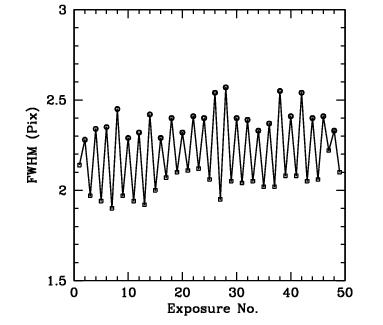
Photometric consistency can be achieved in short exposures made with side A and side B by using a sufficiently large aperture (see WFC3 ISR 2009-20). Fluctuating PSF sizes pose a greater problem for science programs with very bright targets when the results depend on PSF stability or on the highest possible spatial resolution. Such programs may now be able to take short exposures with less vibration using the exposure-level option BLADE=A in APT (introduced in APT version 21.2.2). Testing of this mode is described in WFC3 ISR 2014-09. Since the BLADE option causes additional movement of the shutter mechanism, using only only blade A and bypassing B, its use will be allowed only as an available mode when sufficiently justified. The interested PI should send a scientific justification for using this mode for exposures with less than a specified exposure time to the Contact Scientist or the Program Coordinator, who will forward it to the appropriate instrument scientist for consideration.
Exposure Time Repeatability
Early assessments of the shutter’s exposure time repeatability yielded 4-6 ms r.m.s., easily satisfying the contract specification upper limit of 10 ms r.m.s. (WFC3 ISR 2009-25; WFC3 ISR 2015-12). Those studies, however, were based on extremely short internal flatfield exposures and thus may have been affected by shutter-induced vibrations in the calibration subsystem optics (WFC3 ISR 2018-11). To avoid this effect, a recent calibration program observed an external target with the G280 grism (WFC3 ISR 2023-04). Use of the grism also provided data that allowed for an improved measurement precision since both +1 and -1 orders were captured simultaneously to provide a large dynamic range (the +1 order has ~3x higher throughput than the -1 order, see Section 8.2).
For 1-, 2-, and 4-s exposures, the exposure time repeatability was measured at 2.43 +/- 0.32 ms r.m.s repeatability (WFC3 ISR 2023-04), about 4 times better than required by the specification. The 0.7 sec exposures showed~5.5 ms r.m.s., still satisfying the requirement though worse performance than in the longer exposures, perhaps due to vibrations in the shutter operation (discussed above). The shortest possible UVIS exposures, 0.5 sec, showed ~0.24 ms r.m.s., or about 10 times smaller than the requirement. The improved performance compared to longer exposures could be due to shutter operation as well. For the 0.5 s exposure time (only), the shutter blade performs a continuous sweep across the field of view without stopping, which may help reduce any jitter effects experienced by exposures 0.7 sec or longer, where the shutter blade must rotate open, pause, then rotate shut. Accordingly, we recommend that observers consider substituting a 0.5-s exposure for any 0.7-s exposures that would otherwise be desired.
6.10.5 Droplets
The outer window was contaminated by a mineral residue introduced during acceptance testing of WFC3. These contamination features have been dubbed “droplets” due to their appearance at the time of discovery. In external flat-field images, these features have a strength of approximately ±0.5%. The droplets cause changes in PSF profile, such that flux in the core is redistributed to the near wings. In large-aperture (10 pixel radius) photometry of point sources stepped across a strong window feature, the feature does not significantly increase the photometric scatter. For small-aperture (3 pixel radius) photometry of point sources stepped across a strong window feature, the photometric scatter increases from ~0.5% to ~1%. Quadrant A has the lowest density of features. There are approximately 50, 129, 108, and 179 droplets in quadrants A, B, C, and D, respectively.
The best strategy for mitigating the flat-field features is an appropriate dither pattern. Although there are positions within a flat-field feature that cause systematic errors at the level of a few percent in point source photometry, other positions separated by 20 to 40 pixels show much smaller errors, suggesting that dithers on this scale would be sufficient for most photometric programs. To ensure a point source does not hit a particular feature twice requires larger dithers of approximately 100 pixels, which is the typical diameter of these features.
WFC3 ISR 2008-10 describes the characterization of the droplets and their photometric effects based on ground testing. WFC3 ISR 2009-27 reports that about 30% of droplet positions have shifted by about 1 pixel after launch, but have been stable since then.
6.10.6 Optical Anomalies
In this section, we caution users to be aware of two well-known optical anomalies that may interfere with science objectives.
Additional detector anomalies, ghosts, and defects are detailed on the WFC3 Anomalies webpage for both the UVIS and IR detectors. Also available on the same webpage is a downloadable database of all known anomalies in all non-proprietary WFC3 data, as maintained by the daily monitoring of the WFC3 Quicklook Team (WFC3 ISR 2017-02, WFC3 ISR 2020-02).
Dragon's Breath
In rare cases, the optical system causes stray light from sources outside the CCD FOV to be scattered into images. Analysis of this stray light, known as "dragon's breath", was first presented in WFC3 ISR 2017-02, and more recently explored in WFC3 ISR 2024-09.
The WFC3 team created an interactive plot showcasing the locations of known off-frame sources that caused dragon's breath to occur in previous observations. We share a static view of the tool in use in Figure 6.27; the actual interactive tool is linked under "UVIS Anomalies" on the WFC3 Anomalies webpage. This screenshot shows the interactive "dragon's breath" tool in use. When the user hovers over a source outside of the WFC3/UVIS footprint, an image of the observation pops up, in addition to other information (proposal, observation date, exposure time, V-band magnitude). In the example, the dragon's breath is the vertical shadow in the middle of the detector that crosses the chip gap. In addition, two sets of "figure-8" ghosts are also visible, caused by the bright source in quadrant D (bottom right).
Additionally, an XML overlay is available in APT to assist users planning their observations gauge the likelihood of an off-frame source causing dragon's breath. When viewing in Aladin, load the "Dragons Breath" overlay under "Instrument Fields of Views (FoV)".
Figure 6.27: The dragon's breath interactive tool being used.
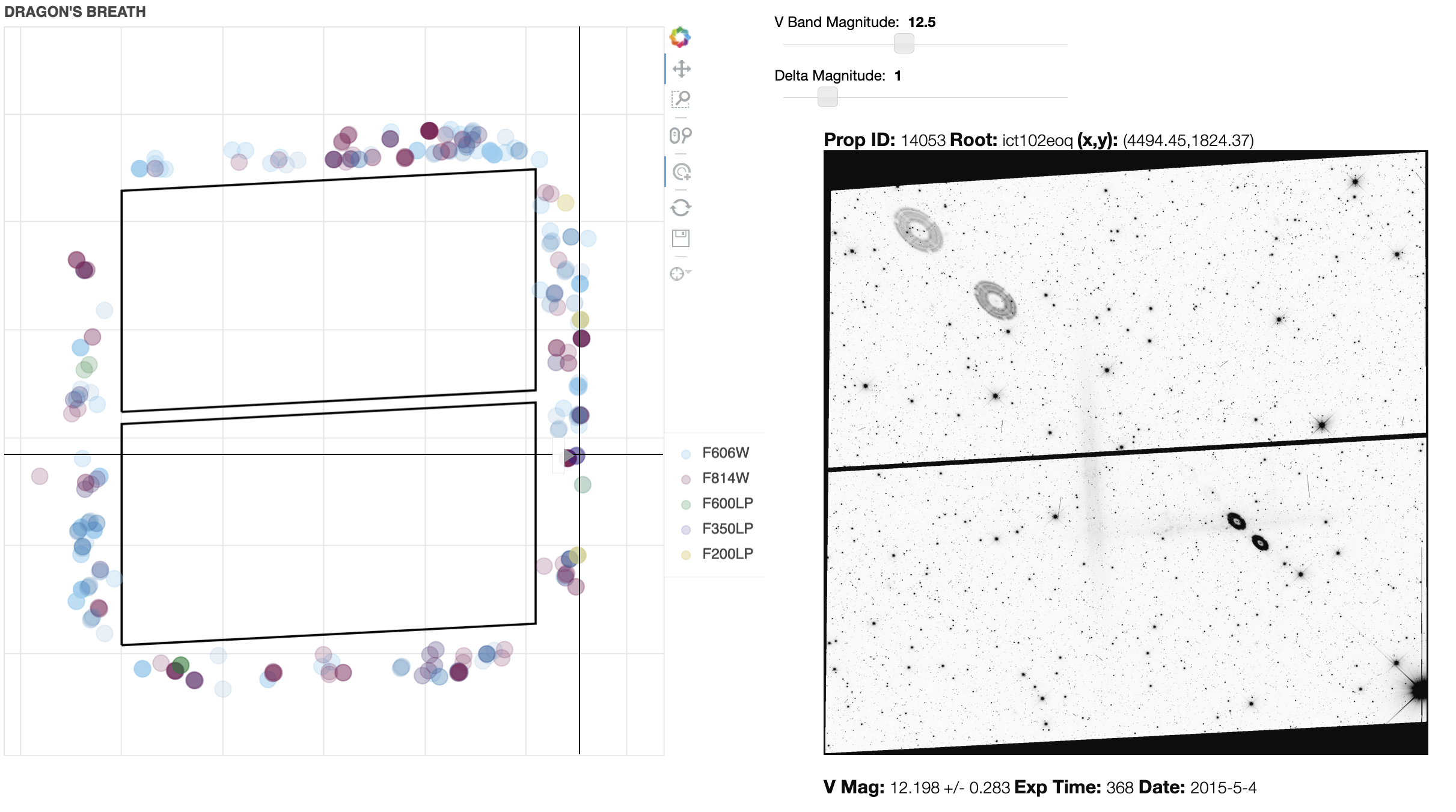
Figure-8 Ghosts
Figure-8 ghosts are caused by reflections between the detector and the two windows of the CCD package. When a bright source is observed in UVIS quadrant D, these ghost reflections may contaminate sources which fall along a diagonal in quadrant A, as shown in Figure 6.28. Users may wish to set orientation restrictions to avoid having ghosts overlap the target of interest. Note: if ORIENTs are necessary, they must be requested in the Phase I proposal.
Additionally, an XML overlay of the projected map of figure-8 ghosts from bright sources in quadrant D is available in APT, for the benefit of users planning their observations. When viewing in Aladin, load the "Window Ghosts" overlay under "Instrument Fields of Views (FoV)".
Figure 6.28: Full-frame observation with two "Figure-8" anomalies.
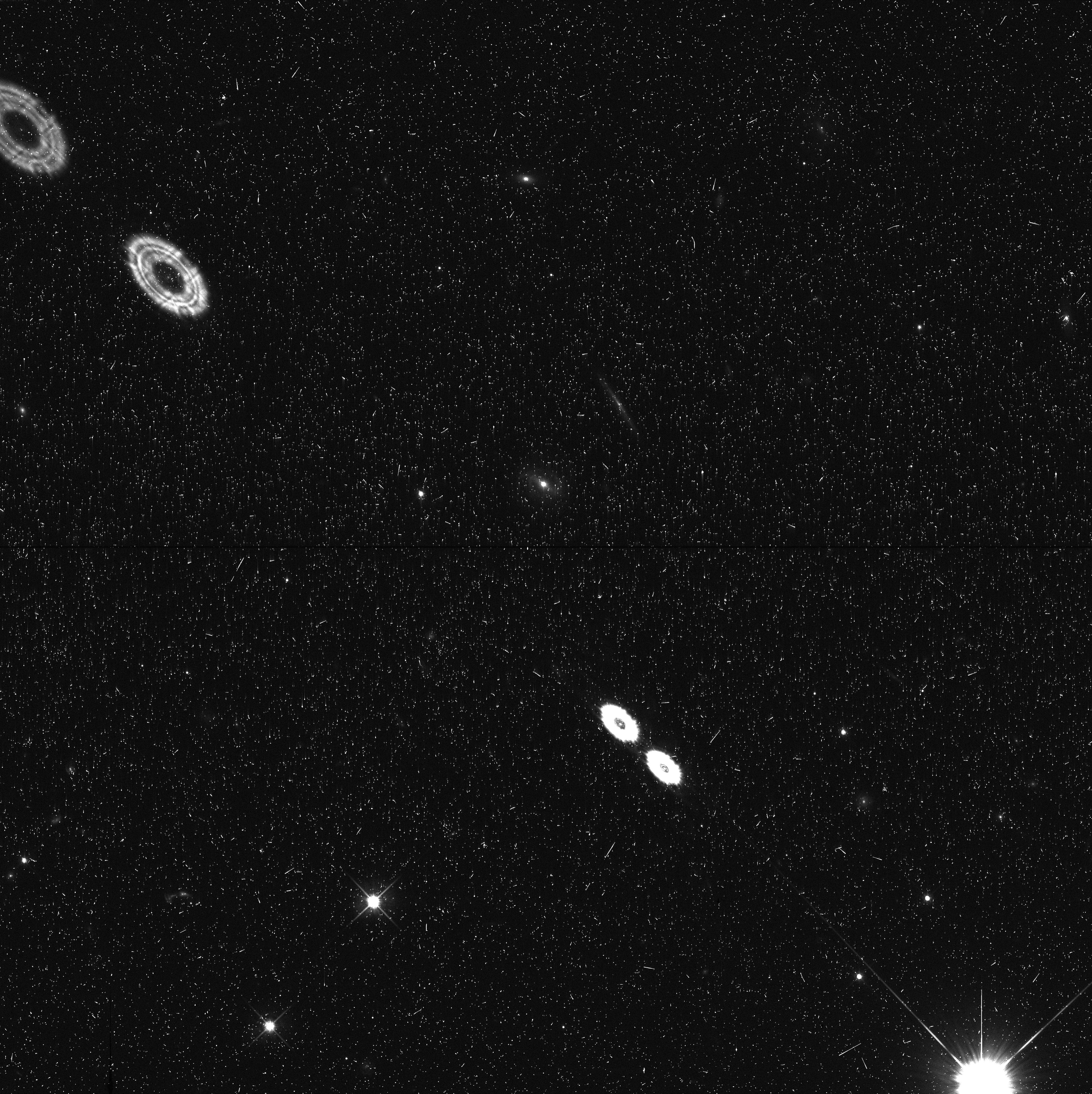
In this full-frame F814W observation (IDI121O8Q from GO Program 15166), the bright source in Quadrant D (bottom right corner) causes two Figure-8 anomalies projected across the diagonal from Quadrant D to Quadrant A.
Additional examples of stray light and other optical anomalies may be found on the WFC3 Anomalies website. |
-
WFC3 Instrument Handbook
- • Acknowledgments
- Chapter 1: Introduction to WFC3
- Chapter 2: WFC3 Instrument Description
- Chapter 3: Choosing the Optimum HST Instrument
- Chapter 4: Designing a Phase I WFC3 Proposal
- Chapter 5: WFC3 Detector Characteristics and Performance
-
Chapter 6: UVIS Imaging with WFC3
- • 6.1 WFC3 UVIS Imaging
- • 6.2 Specifying a UVIS Observation
- • 6.3 UVIS Channel Characteristics
- • 6.4 UVIS Field Geometry
- • 6.5 UVIS Spectral Elements
- • 6.6 UVIS Optical Performance
- • 6.7 UVIS Exposure and Readout
- • 6.8 UVIS Sensitivity
- • 6.9 Charge Transfer Efficiency
- • 6.10 Other Considerations for UVIS Imaging
- • 6.11 UVIS Observing Strategies
- Chapter 7: IR Imaging with WFC3
- Chapter 8: Slitless Spectroscopy with WFC3
-
Chapter 9: WFC3 Exposure-Time Calculation
- • 9.1 Overview
- • 9.2 The WFC3 Exposure Time Calculator - ETC
- • 9.3 Calculating Sensitivities from Tabulated Data
- • 9.4 Count Rates: Imaging
- • 9.5 Count Rates: Slitless Spectroscopy
- • 9.6 Estimating Exposure Times
- • 9.7 Sky Background
- • 9.8 Interstellar Extinction
- • 9.9 Exposure-Time Calculation Examples
- Chapter 10: Overheads and Orbit Time Determinations
-
Appendix A: WFC3 Filter Throughputs
- • A.1 Introduction
-
A.2 Throughputs and Signal-to-Noise Ratio Data
- • UVIS F200LP
- • UVIS F218W
- • UVIS F225W
- • UVIS F275W
- • UVIS F280N
- • UVIS F300X
- • UVIS F336W
- • UVIS F343N
- • UVIS F350LP
- • UVIS F373N
- • UVIS F390M
- • UVIS F390W
- • UVIS F395N
- • UVIS F410M
- • UVIS F438W
- • UVIS F467M
- • UVIS F469N
- • UVIS F475W
- • UVIS F475X
- • UVIS F487N
- • UVIS F502N
- • UVIS F547M
- • UVIS F555W
- • UVIS F600LP
- • UVIS F606W
- • UVIS F621M
- • UVIS F625W
- • UVIS F631N
- • UVIS F645N
- • UVIS F656N
- • UVIS F657N
- • UVIS F658N
- • UVIS F665N
- • UVIS F673N
- • UVIS F680N
- • UVIS F689M
- • UVIS F763M
- • UVIS F775W
- • UVIS F814W
- • UVIS F845M
- • UVIS F850LP
- • UVIS F953N
- • UVIS FQ232N
- • UVIS FQ243N
- • UVIS FQ378N
- • UVIS FQ387N
- • UVIS FQ422M
- • UVIS FQ436N
- • UVIS FQ437N
- • UVIS FQ492N
- • UVIS FQ508N
- • UVIS FQ575N
- • UVIS FQ619N
- • UVIS FQ634N
- • UVIS FQ672N
- • UVIS FQ674N
- • UVIS FQ727N
- • UVIS FQ750N
- • UVIS FQ889N
- • UVIS FQ906N
- • UVIS FQ924N
- • UVIS FQ937N
- • IR F098M
- • IR F105W
- • IR F110W
- • IR F125W
- • IR F126N
- • IR F127M
- • IR F128N
- • IR F130N
- • IR F132N
- • IR F139M
- • IR F140W
- • IR F153M
- • IR F160W
- • IR F164N
- • IR F167N
- Appendix B: Geometric Distortion
- Appendix C: Dithering and Mosaicking
- Appendix D: Bright-Object Constraints and Image Persistence
-
Appendix E: Reduction and Calibration of WFC3 Data
- • E.1 Overview
- • E.2 The STScI Reduction and Calibration Pipeline
- • E.3 The SMOV Calibration Plan
- • E.4 The Cycle 17 Calibration Plan
- • E.5 The Cycle 18 Calibration Plan
- • E.6 The Cycle 19 Calibration Plan
- • E.7 The Cycle 20 Calibration Plan
- • E.8 The Cycle 21 Calibration Plan
- • E.9 The Cycle 22 Calibration Plan
- • E.10 The Cycle 23 Calibration Plan
- • E.11 The Cycle 24 Calibration Plan
- • E.12 The Cycle 25 Calibration Plan
- • E.13 The Cycle 26 Calibration Plan
- • E.14 The Cycle 27 Calibration Plan
- • E.15 The Cycle 28 Calibration Plan
- • E.16 The Cycle 29 Calibration Plan
- • E.17 The Cycle 30 Calibration Plan
- • E.18 The Cycle 31 Calibration Plan
- • E.19 The Cycle 32 Calibration Plan
- • E.20 The Cycle 33 Calibration Plan
- • Glossary